

4 layers87.3 × 56.7 mm
CM4ClusterHat
will127534/Miniature-CM4-Cluster
A dense cluster for four Raspberry Pi Compute Module 4
240 parts96MIT

 carlozepeda-SJSU/Arduino-with-temperature-sensor
Designed and built a custom environmental monitoring system using an Arduino Uno R4 to track temperature, humidity, pressure, and power data in real time. Then advanced the project from a breadboard prototype to a custom PCB shield designed in KiCad.
BME280 Project is an open-source printed circuit board by carlozepeda-SJSU, from the carlozepeda-SJSU/Arduino-with-temperature-sensor repository on GitHub. It is a 2-layer board of 84.1 × 55 mm with 16 parts on 31 nets, routed with 107 tracks and 0 vias.
It is built around the INA219AID and DC-005. Its parts include 5 connectors, 3 switches and 1 IC.
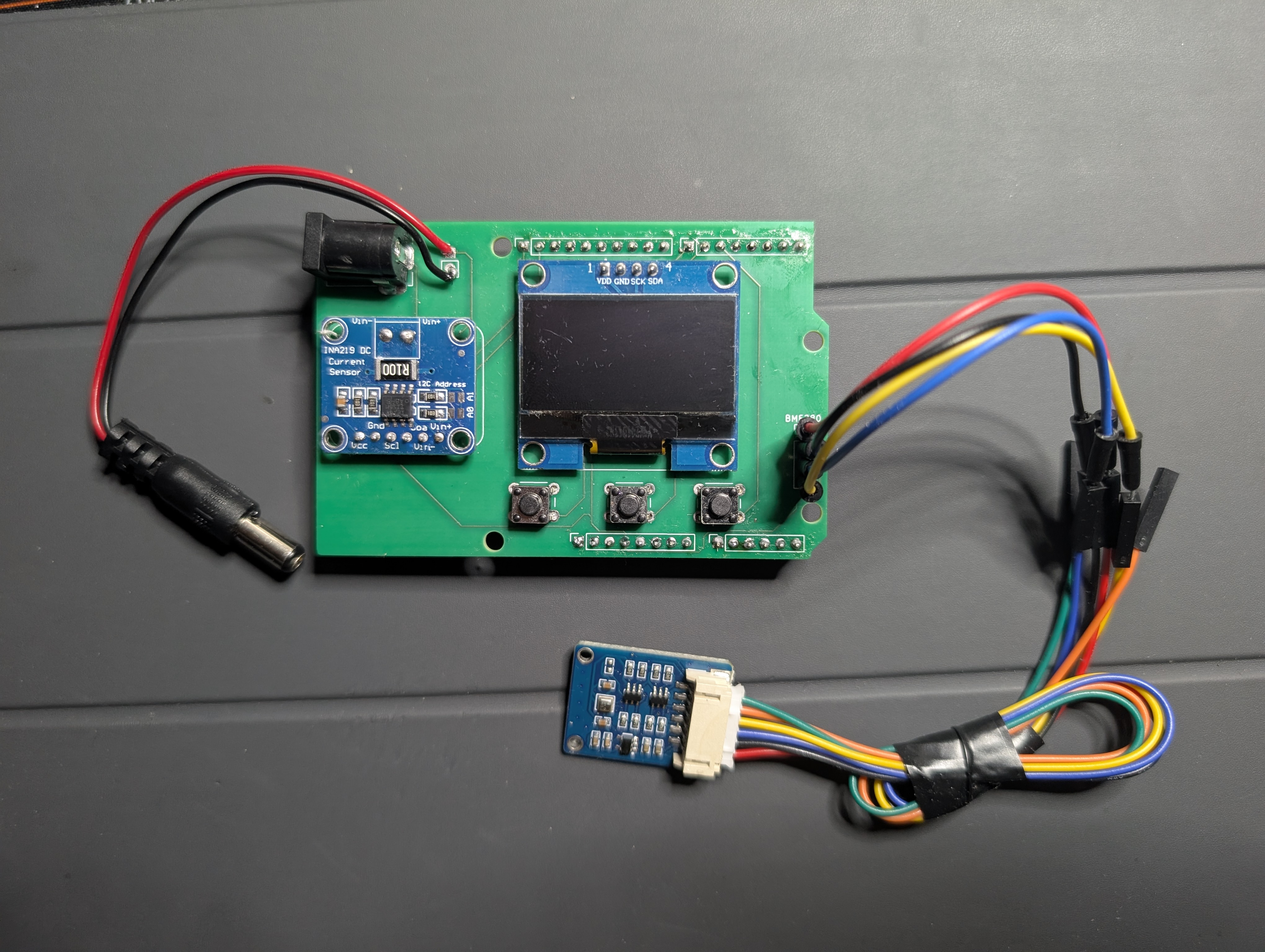
This is a project I worked on to learn how to use the Arduino R4 board while also building a practical device that monitors the temperature, power drawn, time and displays it on a small screen. Throughout the time I worked on this project I gained experience with the Arduino IDE, common electronic used libraries, electronic components, circuit design, and integrated multiple modules into a single working system. What began as a simple breadboard prototype eventually evolved into a complete hardware project. After making sure that the circuit I designed worked, I wanted to make it more professional looking. I created a custom PCB that mounts directly on top of the Arduino Uno R4, creating a much cleaner and more reliable design with fewer jumper wires.
The finished project displays environmental data, power consumption, and the current time on a 1.3-inch OLED display.
The project started with just a breadboard and temperature sensor displaying information on the Arduino IDE. For someone who had never built a project on their own, this was the hardest part. Understanding how libraries work and finding which library is needed for the electronic components was not easy at first. Coding was another part of the project that I was not confident about, however as I kept learning more and expanding the project, I gained more knowledge and confidence. Once everything implemented was working as intended, I decided that it was time to take the next step.
Features included:
While the breadboard prototype was working as intended, I wanted to make it look less messy and more like a finished product. So I designed a custom PCB in KiCad that mounts directly on top of the Arduino Uno R4. This part helped me understand the KiCAD work flow. From deciding where to place the components, to finding the right footprints. This part was a lot of trial and error, but I am satisfied with the end product.
The PCB includes:
Throughout this project I learned how to:
The completed breadboard prototype showing all connected components.
The completed PCB HAT assembled
| Qty | Value | Footprint | References |
|---|---|---|---|
| 4 | MountingHole_3.2mm | Arduino_MountingHole:MountingHole_3.2mm | MH1, MH2, MH3, MH4 |
| 3 | SW_Push | Button_Switch_THT:SW_PUSH_6mm_H4.3mm | SW1, SW2, SW3 |
| 1 | Analog | Connector_PinSocket_2.54mm:PinSocket_1x06_P2.54mm_Vertical | J3 |
| 1 | Conn_01x02_Pin | Connector_PinHeader_2.54mm:PinHeader_1x02_P2.54mm_Vertical | Barrel_Jack_Vin2 |
| 1 | Conn_01x04_Pin | Connector_PinHeader_2.54mm:PinHeader_1x04_P2.54mm_Vertical | BME280 |
| 1 | DC-005 | 5_DC-005:NINIGI_DC-005 | J6 |
| 1 | Digital/PWM | Connector_PinSocket_2.54mm:PinSocket_1x08_P2.54mm_Vertical | J4 |
| 1 | Digital/PWM | Connector_PinSocket_2.54mm:PinSocket_1x10_P2.54mm_Vertical | J2 |
| 1 | INA219 | INA219:MODULE_INA219 | U1 |
| 1 | OLED_128X64_1.3_I2C | 2_SH1106 OLED:LCD_OLED_128X64_1.3_I2C | DS1 |
| 1 | Power | Connector_PinSocket_2.54mm:PinSocket_1x08_P2.54mm_Vertical | J1 |
will127534/Miniature-CM4-Cluster
A dense cluster for four Raspberry Pi Compute Module 4


PotatoX/Band_Saw_Conversion
Cheap benchtop wood cutting band saw -> decent metal cutting

It measures 84.1 × 55 mm and has 2 copper layers, 1.6 mm thick.
16 parts, built around the INA219AID and DC-005. The full list of its parts is on this page, with links to each part's symbol and footprint where PCBKit's library has them.
From the carlozepeda-SJSU/Arduino-with-temperature-sensor repository on GitHub, at the commit this page was made from: the board is BME280_Project.kicad_pcb and its schematic BME280_Project.kicad_sch. PCBKit opens the board in the browser, with nothing to install.
Its repository states no licence, so its author keeps all rights: ask carlozepeda-SJSU before reusing the design.