2 layers47.5 × 75 mm

 calphool/JMR-8001
JMR-800 project, clone of PG-800 hardware
PG800-JMR is an open-source printed circuit board by calphool, from the calphool/JMR-800 repository on GitHub. It is a 2-layer board of 93.5 × 124.5 mm with 61 parts on 144 nets, routed with 993 tracks and 220 vias.
It is built around the CD74HC4067M, 74HC595 and LM1117T-3.3, with the BSS138 among its other parts. Its parts include 17 connectors, 15 resistors, 12 capacitors, 7 ICs and 3 transistors.


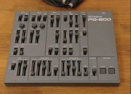
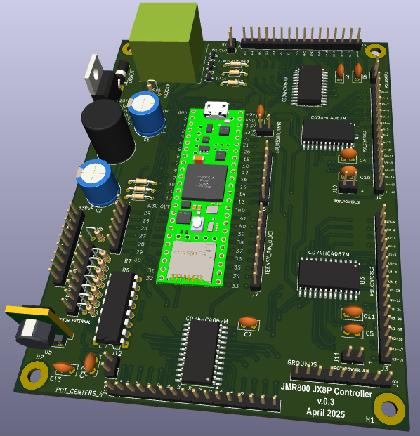
JMR-800 is a modern, open-source clone of the Roland PG-800 hardware programmer, built around the Teensy 4.1 microcontroller. It provides real-time parameter control for vintage Roland synthesizers such as the JX-8P, MKS-70, and JX-10 using the original PG-800 communication protocol.
The JMR-800 replicates the original PG-800's functionality and physical interface, enabling direct, tactile editing of synthesizer parameters through a hands-on control surface.
This project is currently in active development. Basic communication and parameter changes are being validated. Contributions, forks, and collaboration are welcome.
April 10, 2025
Redesigned PCB to get rid of the 74HC165 input bit shifter and replaced it with another analog mux/demux. The total number of parameters that can be tweaked with the JX8P with the Vecoven PWM enhancement is 52. So, I need to support at least 52 pots, and I can only support 48 with three muxes. I mean there are enough ADCs on the Teensy 4.1, that I probably could hack it and get those last 4 with separate ADC pins on the Teensy, but that's a pretty ineligant design, so I'll just add another mux/demux, get rid of the bit shifter, and limit my use of push buttons to just a few. I technically only need one or two (the PG-800 only has 2), but I'll probably come up with a few odds and ends to implement (like maybe a way to load a whole sound from the JMR-800 by tweaking all of the parameters based on loading something from an SD card or something), so having a few more won't hurt.
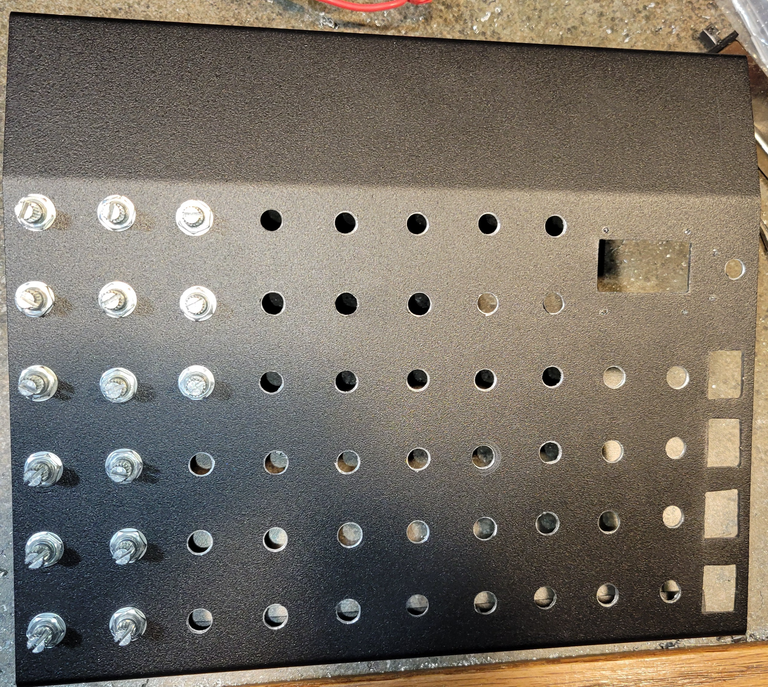
Decided to lay out the whole interface with my 3D printer as a template first. This will allow me to cut cleaner holes into the aluminum case I think. I'm using an aluminum case from Jameco that looks pretty retro / period correct.
April 14, 2025
Worked on the aluminum case a bit today. Ran out of potentiometers, so ordered some more.
April 17, 2025
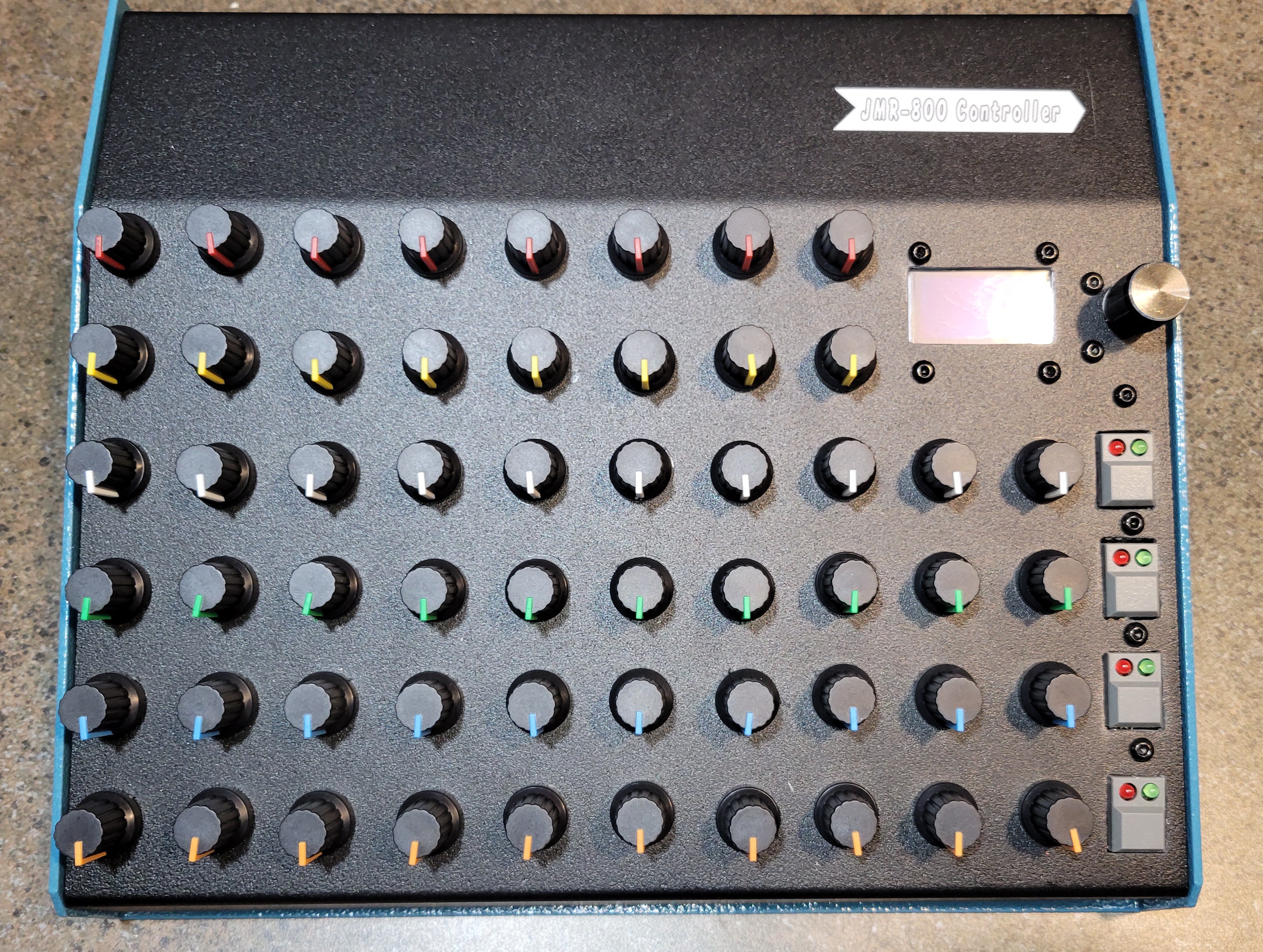
Worked on the case some more. Completed the potentiometer installation, got some knobs and installed them, though I don't like the fact that I didn't get
an even number of red and blue, so I need to get another kit of them. I also don't like the white ones, I think I'll remove those and replace with black.
Finally, I couldn't find black 3mm screws, so I had to use stainless steel. I'm going to change that, it ruins the asthetic.
Once I get all that settled, it's back to the software and firmware. I redesigned the PCB about a week ago, but I think I'm going to need to do a slight additional redesign. The four push buttons have two LEDs on them, a red one and a green one. I really don't know exactly what I'm going to use them for yet, but I'm going to need an output shift register to manage all 8 of them (as well as current limiting resistors for each one, which would probably be best on the board rather than dangling and inline with the wires.
The software already works in a prototype way (two potentiometers that I tested with), so hopefully there won't be any surprises when I get all of them running. I also added an additional 3.3V regulator that's optional on the new design, since I'm not altogether sure that the tiny little regulator on the Teensy can handle all the load I'm throwing at it.
April 29, 2025
Got the new PCB and the rest of the hardware put together. I wrote some temporary code that implements a "TEST MODE" that shows the condition of all the knobs.
May 3, 2025
I've updated the code quite a bit. It now has 3 modes. Run mode, Test mode, and Config mode. I've been working on the Config mode. You can change into these different modes by pressing Button 1 and Button 2 simultaneously. When you configure a knob, you can change its name, its command byte, and select which type of knob it is. I've got the command byte selection finished, and I'm working on the name update code now. Once I get all the config stuff finished (perhaps this evening), I'll begin working on the Run mode. This stuff was prototyped already with the earlier version of the board, so I'm pretty sure the code for interacting with the synth will work.
I may eventually implement some kind of "preset mode" that allows you to scroll through a given configuration of knobs, select it, and it would play all 56 knobs into the synthesizer. This may be a submenu of the Run mode. One step at a time of course...
May 5, 2025
It's alive! I got the first fully functional code put together and just did about 15 minutes of testing. It definitely works. Though there's plenty to tweak. Right now it's ignoring the parameter type and just sending values from 0 - 127, which does work, but it causes the screen to flicker on the synth for the parameters that only have a few set values. I'm also wondering about how to manage noise from the potentiometers. Although I used a smoothing algorithm, which does make them a lot less noisy, you still get odd little blips from time to time, and since they take whatever value the knob is at at the time, if you've just changed patches it can make a dramatic change to the sound. I wonder if I should implement a kind of "lock / unlock" with one of the switches. I could use green for "I'm unlocked and sending data to the synth" vs red for "I'm currently locked and not sending anything to the synth."
Lots and lots of small tweaks to work on now, but at least it's working. The PWM mod that I installed from https://www.vecoven.com/superjx/styled/pwm.html is pretty cool, especially with knobs that tweak its behavior in real time.
The other tweaks that the vecoven upgrade made to my firmware on my synth still takes some getting used to. I'm going to have to read through the manuals for the vecoven upgrade really carefully, because it's pretty easy to get lost in the menus. Maybe I could implement a "notepad" in the OLED screen of the JMR800 so it can remind me of stuff for the Vecoven upgrade.
One thing that I noticed that I'm going to have to deal with is the fact that not all the pots return the full range from 0 - 127 when sent through the ADC. They came in a big bag from Aliexpress, so they're probably pretty low quality. I'm going to need to implement some way to measure their min and max values, probably in the config mode, and then scale the pot value for each pot in software.
May 11, 2025
Finished all the screen stuff for Run mode, which is a pretty big milestone. Also added an SVG file that represents the console layout. Working on an overlay using a Glowforge and acrylic.
May 14, 2025
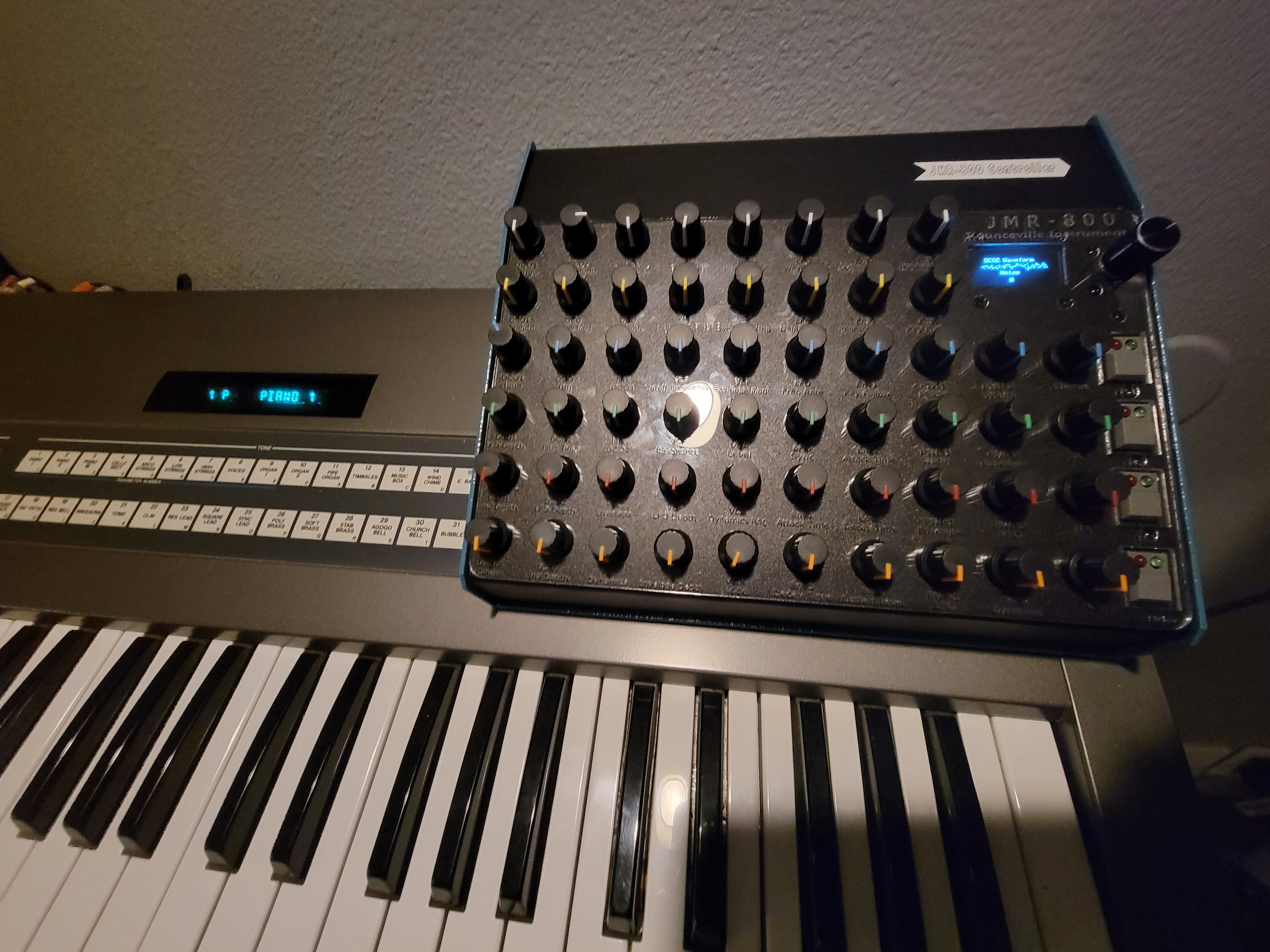
May 22, 2025
I'm beginning to consider a major refactor of the software. It all works pretty well, but there are some things I'd like to do that require a cleaner code base. Basically I cobbled together the different system modes using a sloppy FSM rather than doing proper object oriented development whereby I set up modes as objects, and modes have screens, and screens have widgets, and widgets interact with controls, and so on. By doing this, I'd have an infinitely more expandable user interface, and I really would like to implement a few interesting ideas.
First, I'd like to make it so that there are a collection of pre-sets that can be played into the JX8P on demand (like button 2 does right now with the default sound load, but with many many different presets). The other thing I'd really like to do is implement something analogous to an arpeggiator, but rather than changing notes, it would change settings on a parameter. For example, let's say you want to vary any arbitrary parameter (say something weird like chorus) with something like an LFO. Let us further consider that you don't want to use one of the three or four LFO options available in the synth hardware itself, bur instead you want to be able to apply any arbitrary waveform to that chorus. Although the "waveform" will be small (only 32 steps), it can take any form, and you simply draw the waveform in. Then, when you go to a parameter for a given control, you depress the encoder button, and it pops up with a menu that lets you choose which stepper-LFO you want to use for this parameter.
All of this will require some significant refactoring. I also want to introduce a microSD to the Teensy so that all this stuff can be stored and retrieved.
Keep an eye out for a major update to the code base soon.
This project is released under the MIT License.
| Qty | Value | Footprint | References |
|---|---|---|---|
| 10 | 0.1uF | Capacitor_THT:C_Disc_D5.0mm_W2.5mm_P2.50mm | C4, C5, C6, C7, C8, C9, C10, C11, C12, C13 |
| 8 | 220 | Resistor_THT:R_Axial_DIN0204_L3.6mm_D1.6mm_P2.54mm_Vertical | R1, R2, R3, R4, R5, R6, R7, R8 |
| 6 | 10k | Resistor_THT:R_Axial_DIN0204_L3.6mm_D1.6mm_P7.62mm_Horizontal | R9, R10, R11, R12, R13, R14 |
| 4 | CD74HC4067M | Package_SO:SOIC-24W_7.5x15.4mm_P1.27mm | U2, U3, U4, U6 |
| 4 | MountingHole_Pad | MountingHole:MountingHole_3.5mm_Pad | H1, H2, H3, H4 |
| 3 | BSS138 | Package_TO_SOT_SMD:SOT-23 | Q1, Q2, Q3 |
| 1 | 100uF / 30v | Capacitor_THT:CP_Radial_D10.0mm_P2.50mm | C1 |
| 1 | 1N5819 | Diode_THT:D_DO-15_P10.16mm_Horizontal | D1 |
| 1 | 3.3V_BUS | Connector_PinHeader_2.54mm:PinHeader_1x09_P2.54mm_Vertical | J14 |
| 1 | 3.3V_ONBOARD_JUMPER | Connector_PinHeader_2.54mm:PinHeader_1x02_P2.54mm_Vertical | J16 |
| 1 | 330uF | Capacitor_THT:CP_Radial_D10.0mm_P5.00mm | C2 |
| 1 | 330uH | Inductor_THT:L_Radial_D12.0mm_P5.00mm_Fastron_11P | L1 |
| 1 | 4.1 | JoesStuff:Teensy4.1 | TEENSY1 |
| 1 | 5V | Connector_PinHeader_2.54mm:PinHeader_1x02_P2.54mm_Vertical | J15 |
| 1 | 720 | Resistor_THT:R_Axial_DIN0204_L3.6mm_D1.6mm_P2.54mm_Vertical | R15 |
| 1 | 74HC595 | Package_DIP:DIP-16_W7.62mm | U7 |
| 1 | DIN-6 | JoesStuff:DIN-6 | J1 |
| 1 | GROUNDS | Connector_PinHeader_2.54mm:PinHeader_1x09_P2.54mm_Vertical | J8 |
| 1 | LED_REG_CONN | Connector_PinHeader_2.54mm:PinHeader_1x08_P2.54mm_Vertical | J17 |
| 1 | LM1117T-3.3 | Package_TO_SOT_THT:TO-220-3_Vertical | U8 |
| 1 | LM2575-5BT | Package_TO_SOT_THT:TO-220-5_Vertical | U1 |
| 1 | POT_CENTERS_1 | Connector_PinHeader_2.54mm:PinHeader_1x16_P2.54mm_Vertical | J2 |
| 1 | POT_CENTERS_2 | Connector_PinHeader_2.54mm:PinHeader_1x16_P2.54mm_Vertical | J3 |
| 1 | POT_CENTERS_3 | Connector_PinHeader_2.54mm:PinHeader_1x16_P2.54mm_Vertical | J4 |
| 1 | POT_CENTERS_4 | Connector_PinHeader_2.54mm:PinHeader_1x16_P2.54mm_Vertical | J13 |
| 1 | POT_POWER_1 | Connector_PinHeader_2.54mm:PinHeader_1x02_P2.54mm_Vertical | J9 |
| 1 | POT_POWER_2 | Connector_PinHeader_2.54mm:PinHeader_1x02_P2.54mm_Vertical | J10 |
| 1 | POT_POWER_3 | Connector_PinHeader_2.54mm:PinHeader_1x02_P2.54mm_Vertical | J11 |
| 1 | POT_POWER_4 | Connector_PinHeader_2.54mm:PinHeader_1x02_P2.54mm_Vertical | J12 |
| 1 | TEENSY_PIN_BLK1 | Connector_PinHeader_2.54mm:PinHeader_1x06_P2.54mm_Vertical | J6 |
| 1 | TEENSY_PIN_BLK2 | Connector_PinHeader_2.54mm:PinHeader_1x07_P2.54mm_Vertical | J5 |
| 1 | TEENSY_PIN_BLK3 | Connector_PinHeader_2.54mm:PinHeader_1x09_P2.54mm_Vertical | J7 |

cva68/ESPBreadboardRobot
Peripheral and breakout board for the ESP-32, with firmware designed for use with Microsoft MakeCode


CainPatel/diy-ert
A $150 four-electrode earth resistivity meter (Wenner array): Arduino, AD620, ADS1115. Documented failure-first as an engineering log.


KilowattSynthesis/Braille-Display-CAD
Experimental design for a braille display using build123d CAD in Python

KilowattSynthesis/Braille-Display-Column-Rods
Braille display POC using tiny stepper motors to drive columns of the display
It measures 93.5 × 124.5 mm and has 2 copper layers, 1.6 mm thick.
61 parts, built around the CD74HC4067M, 74HC595, LM1117T-3.3 and BSS138. The full list of its parts is on this page, with links to each part's symbol and footprint where PCBKit's library has them.
From the calphool/JMR-800 repository on GitHub, at the commit this page was made from: the board is PG800-JMR/PG800-JMR.kicad_pcb and its schematic PG800-JMR/PG800-JMR.kicad_sch. PCBKit opens the board in the browser, with nothing to install.
Its repository states no licence, so its author keeps all rights: ask calphool before reusing the design.