2 layers94.7 × 117.8 mm
Bop It
calebmarting/os2026-badge
Schematics and firmware for the Open Sauce 2026 Badge and SAOs
11 parts23MIT

 calebmarting/os2026-badge23
Schematics and firmware for the Open Sauce 2026 Badge and SAOs
T Piece Kicad is an open-source printed circuit board by calebmarting, from the calebmarting/os2026-badge repository on GitHub, published under the MIT licence. It is a 2-layer board of 69.8 × 40.4 mm with 82 parts on 84 nets, routed with 1,235 tracks and 108 vias.
It is built around the ATSAMD21G18A-AU, MCP6001T-I/OT(MS) and SC7A20HTR, with the KT-0603R, CG0603MLC-05E and FV21X472K102ECG among its other parts. Its parts include 31 resistors, 22 capacitors, 7 diodes, 4 ICs and 2 switches. It belongs with the lEDs and displays boards and the SAM D and SAM boards of this library.


Schematics and firmware for the Open Sauce 2026 Badge and SAOs
At least two people that we know of hacked the badge Saturday night, and showed up with 4 new games on Sunday! You'll find their code available in the putnam hack folder. And more instructions on how to install their code and the other examples in the examples folder.
We want to enable more people to make cool things after the event, so this repo contains everything that you need to make cool things with the badge and SAOs. This badge is just an Arduino MKR Zero in a Trench Coat so you can do what you want! Please post any cool makes and bring them to Open Sauce next year!
General layout and pins for the Arduino MKR Zero
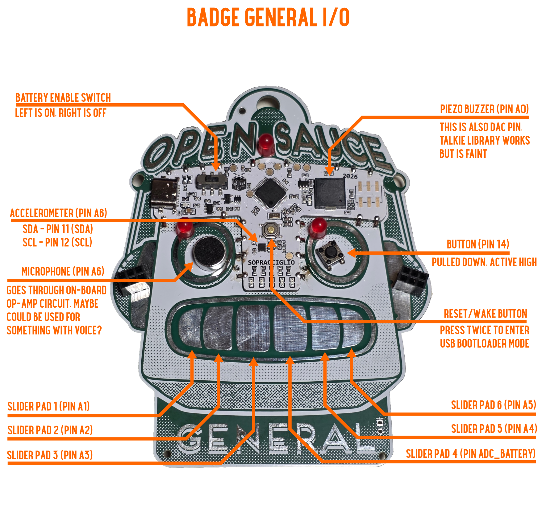
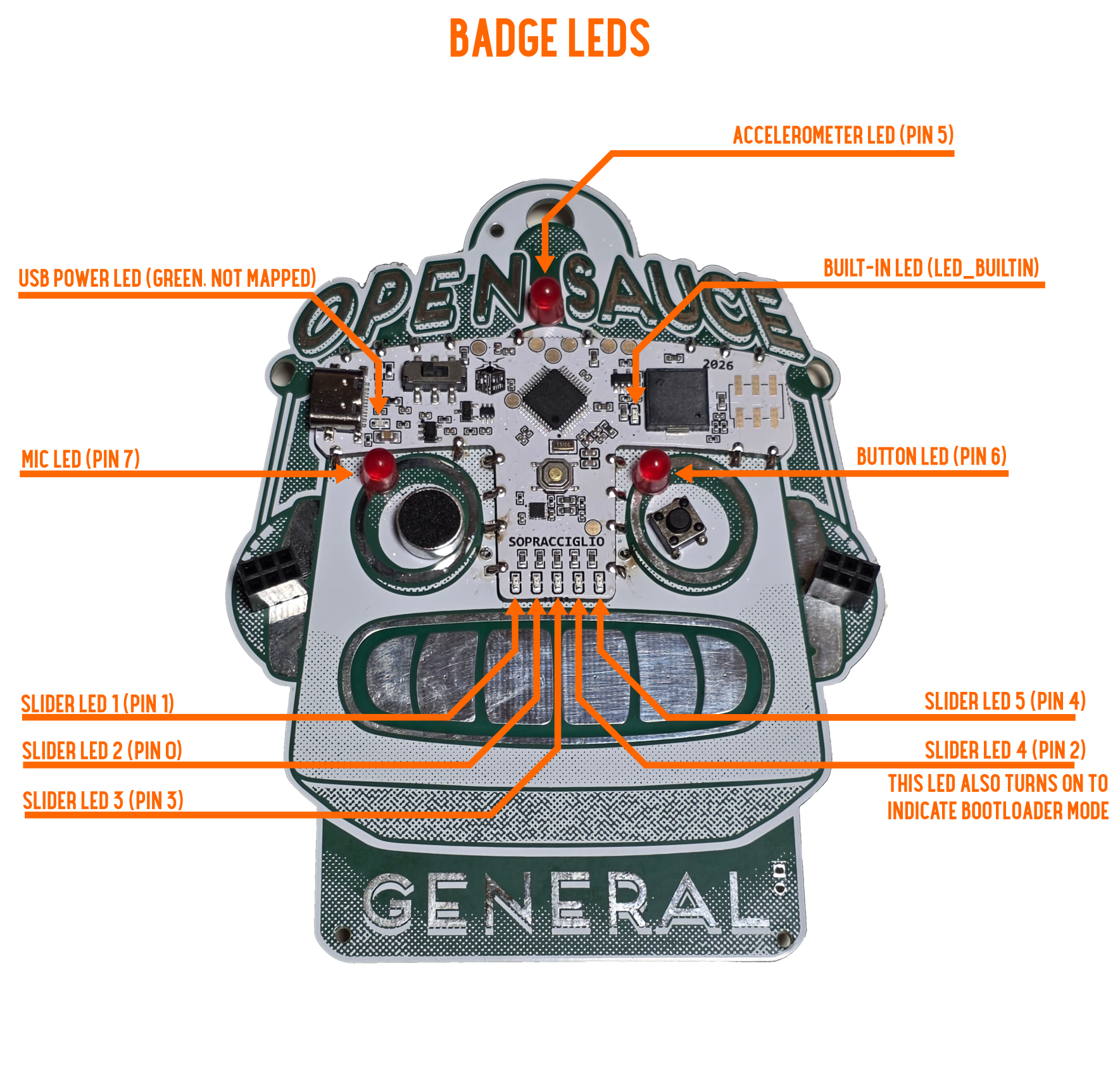
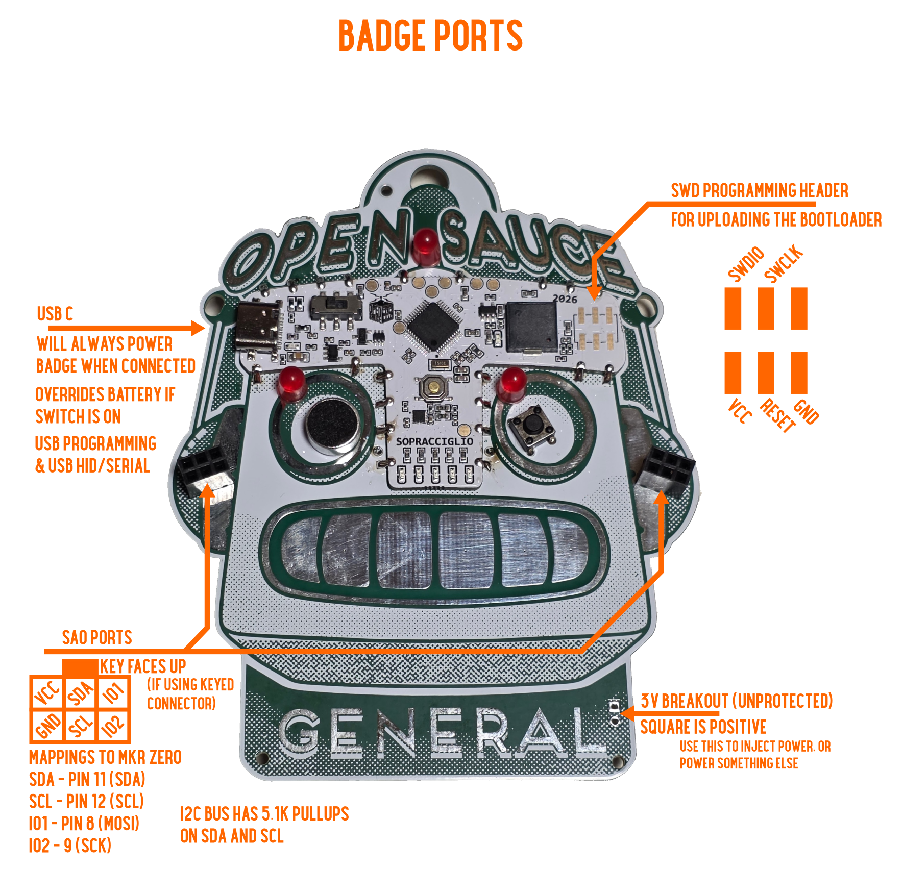
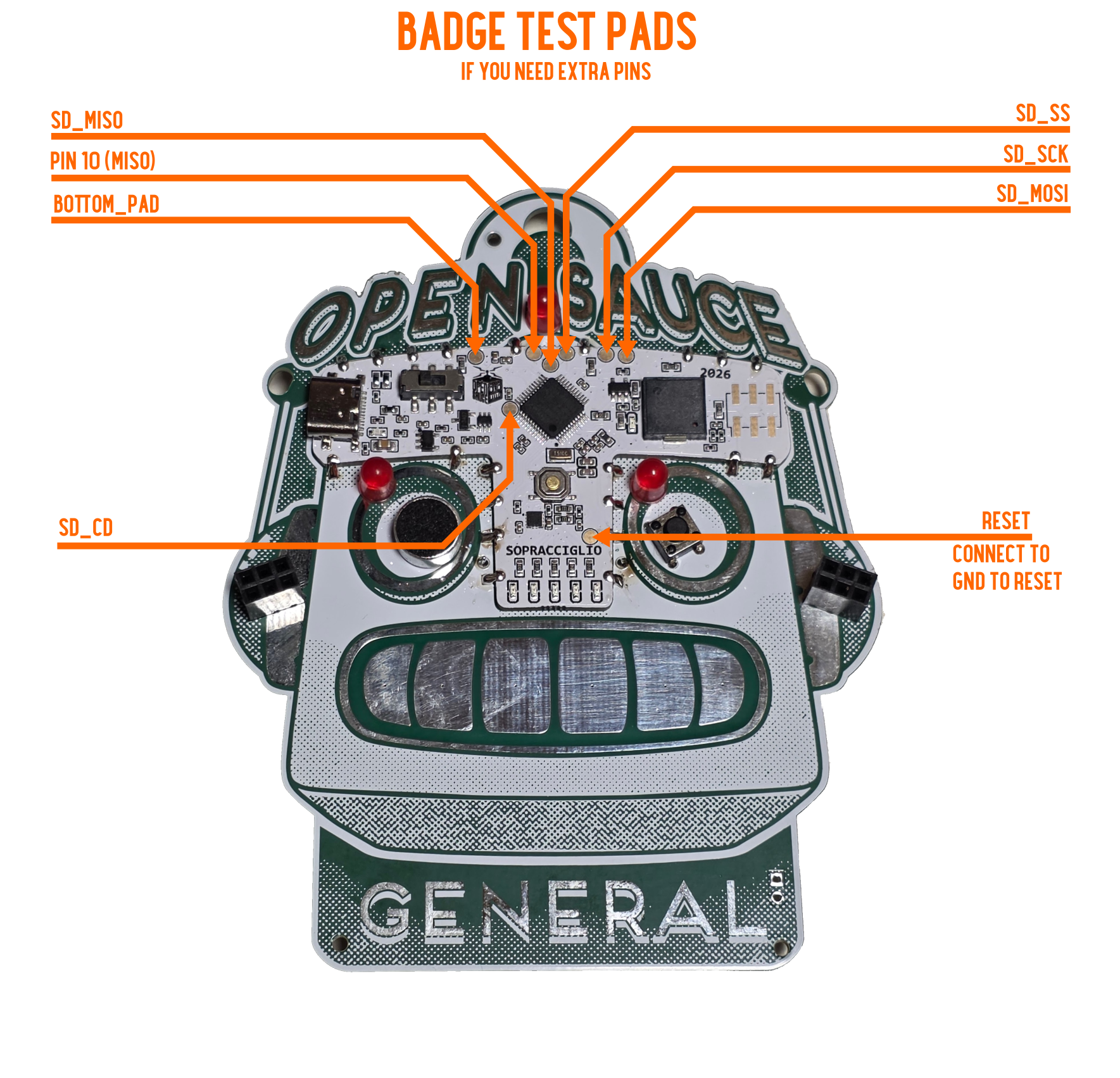
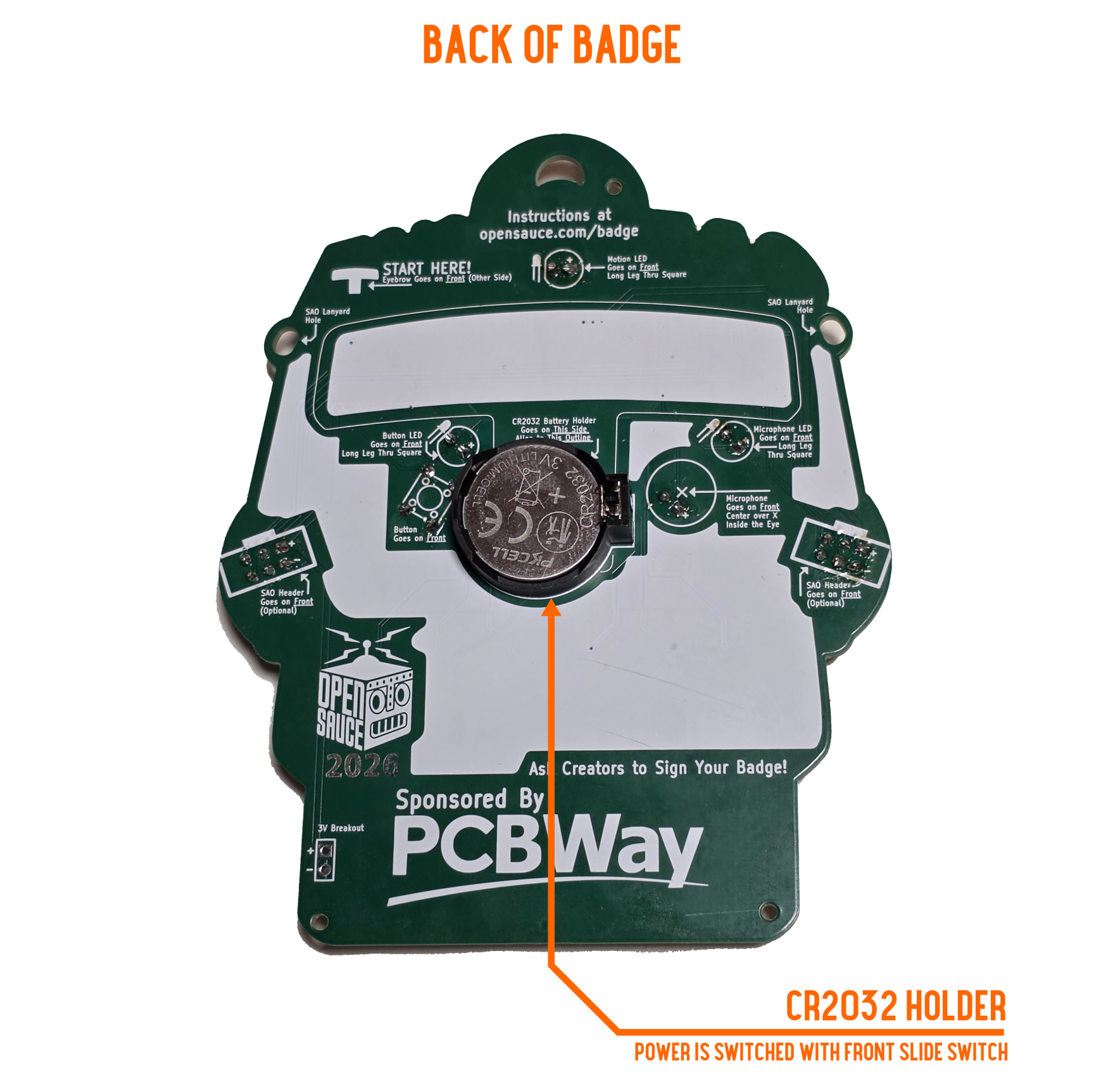
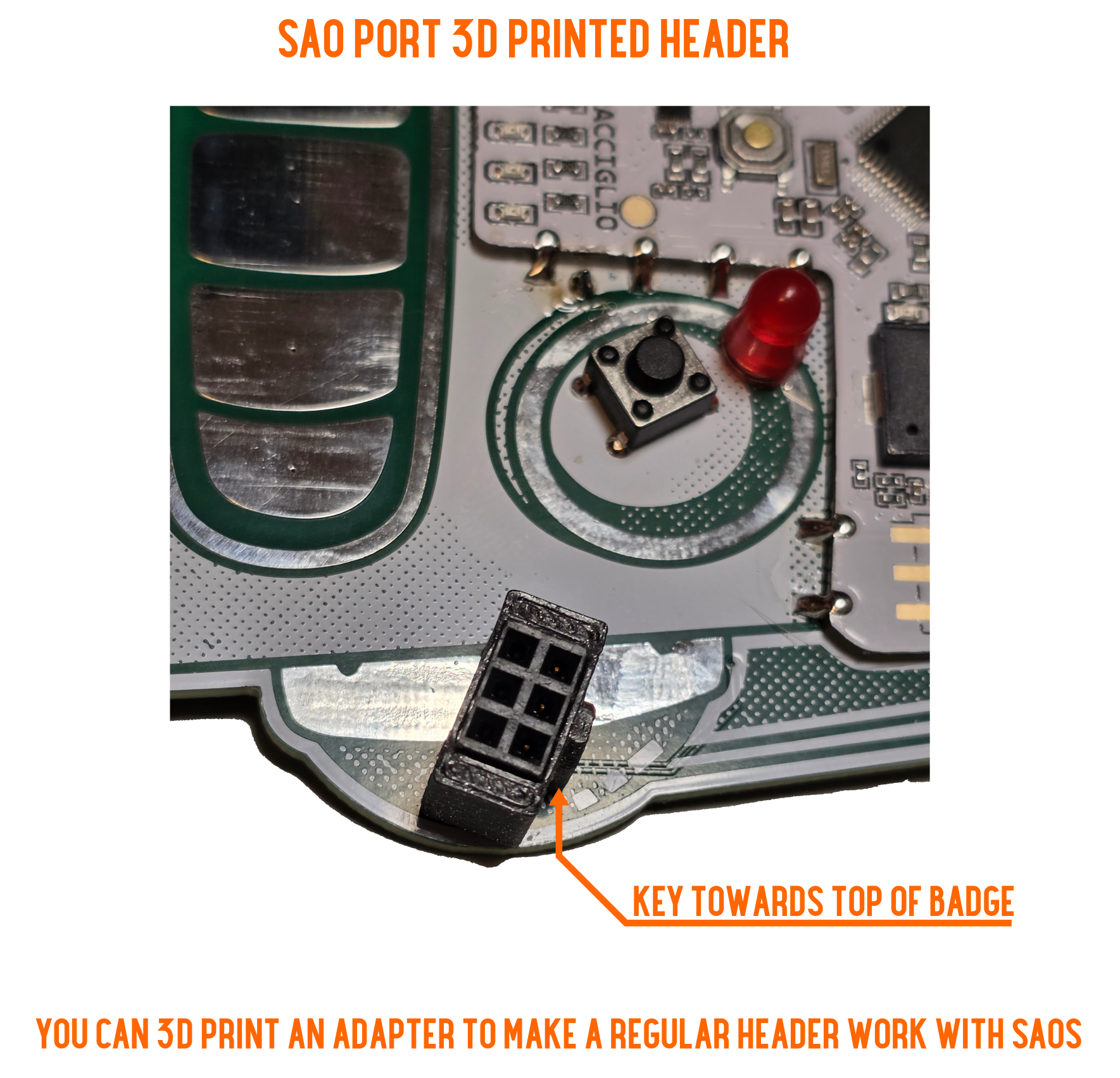
The stl file to convert a regular 2x3 header can be found here
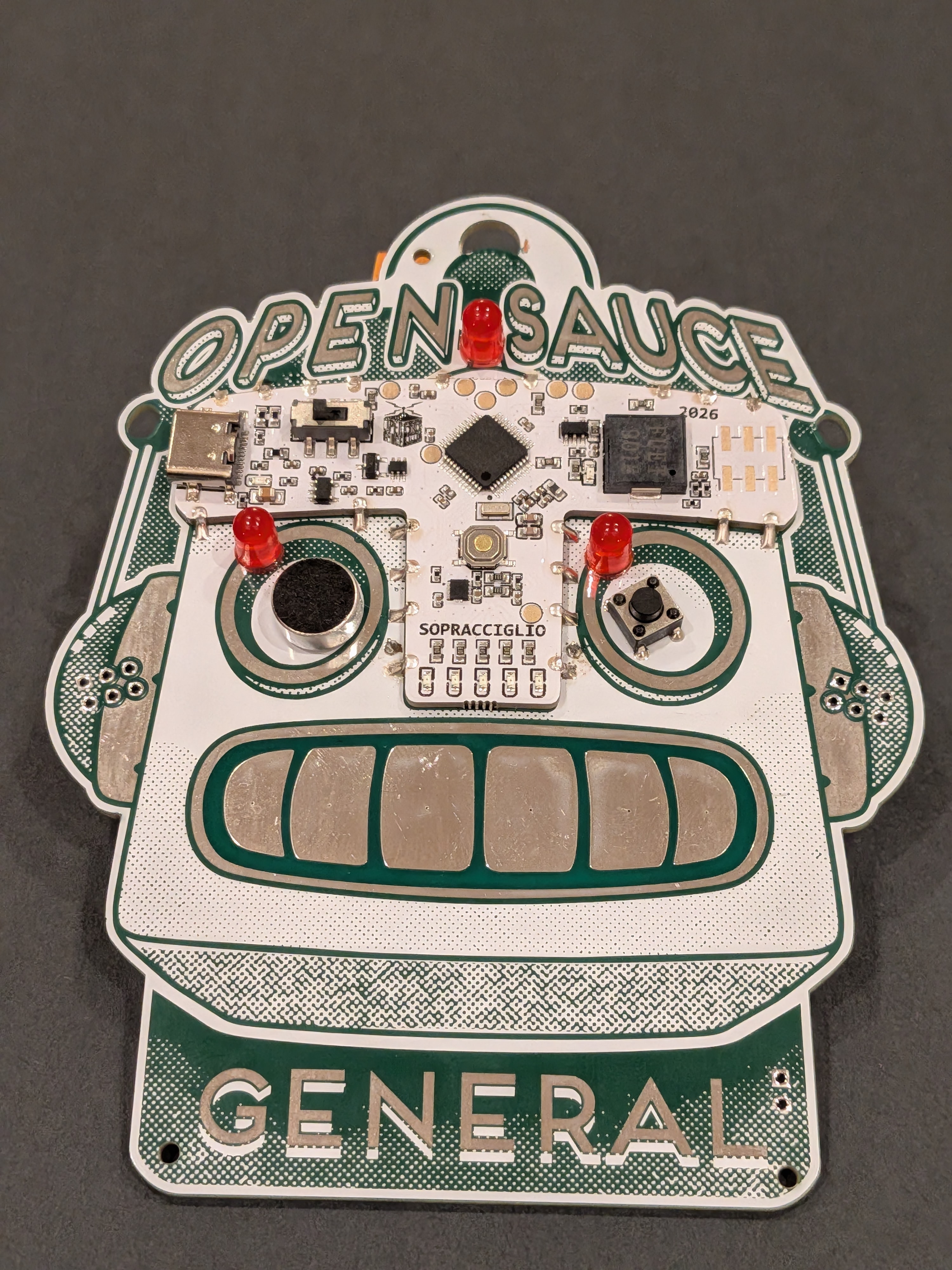
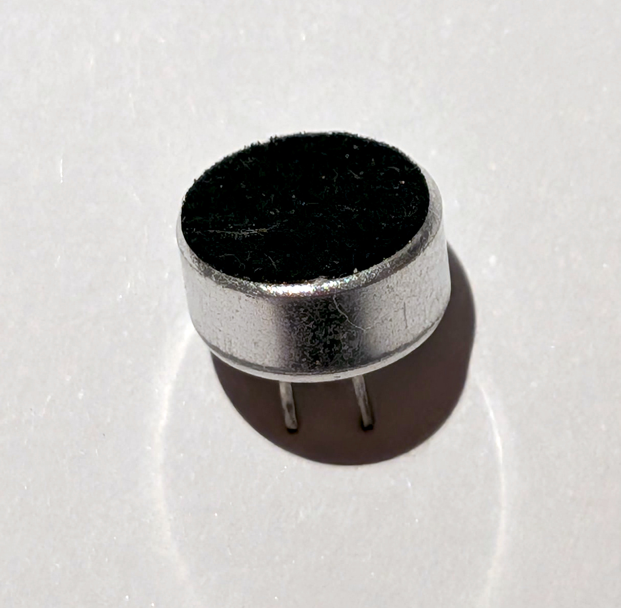
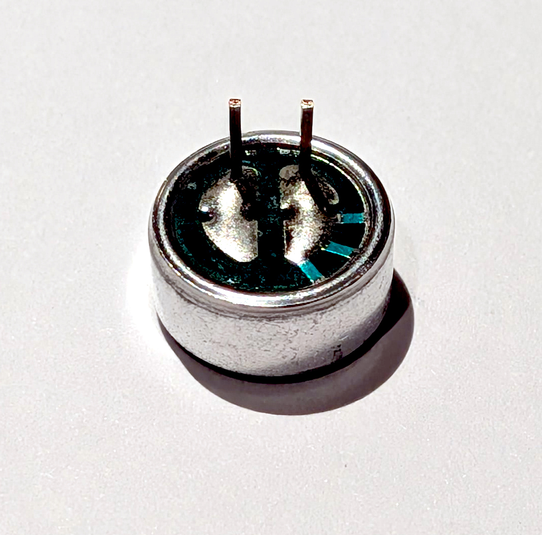
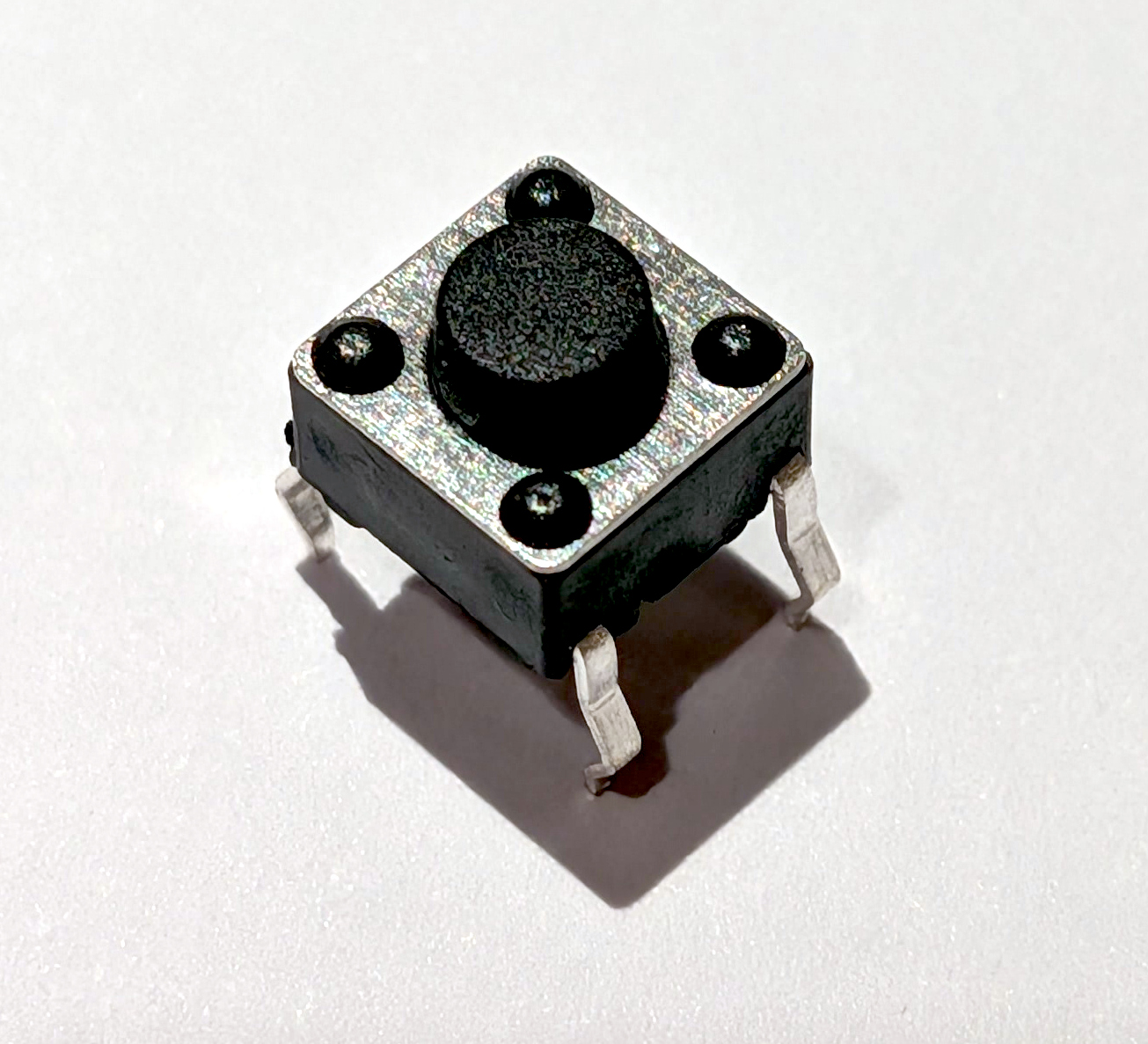
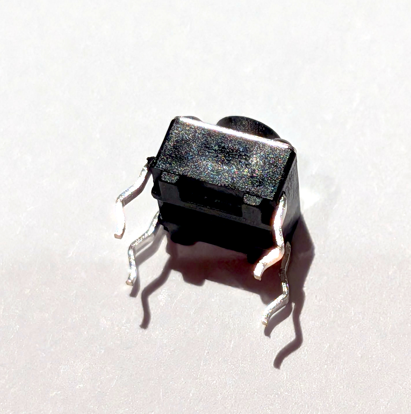
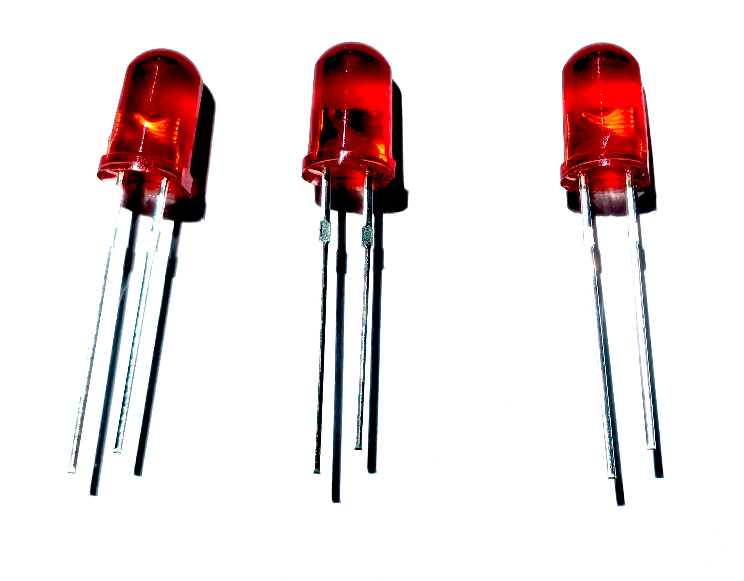
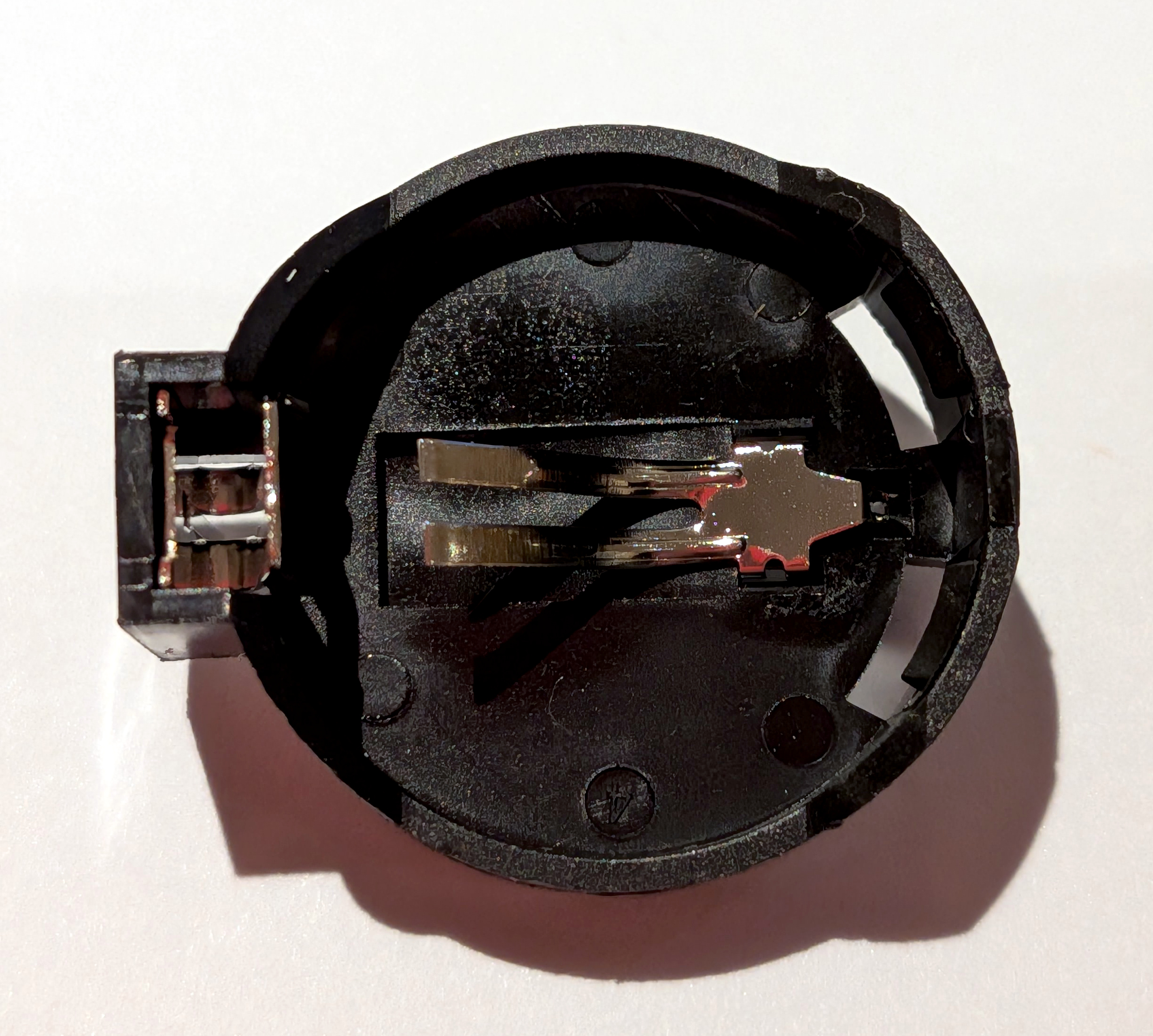
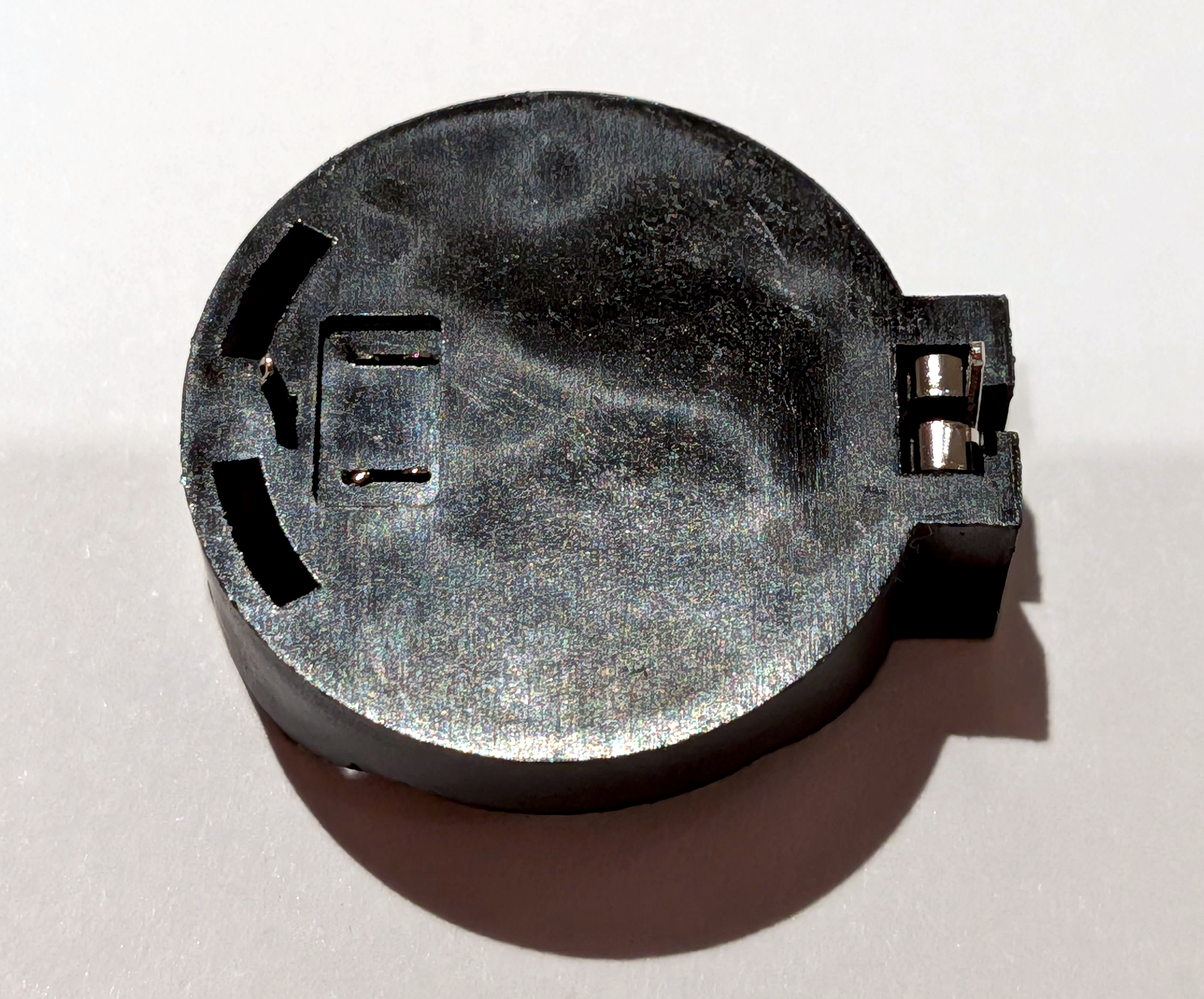
Optional:
Set the badge face up, and take off the Lanyard.
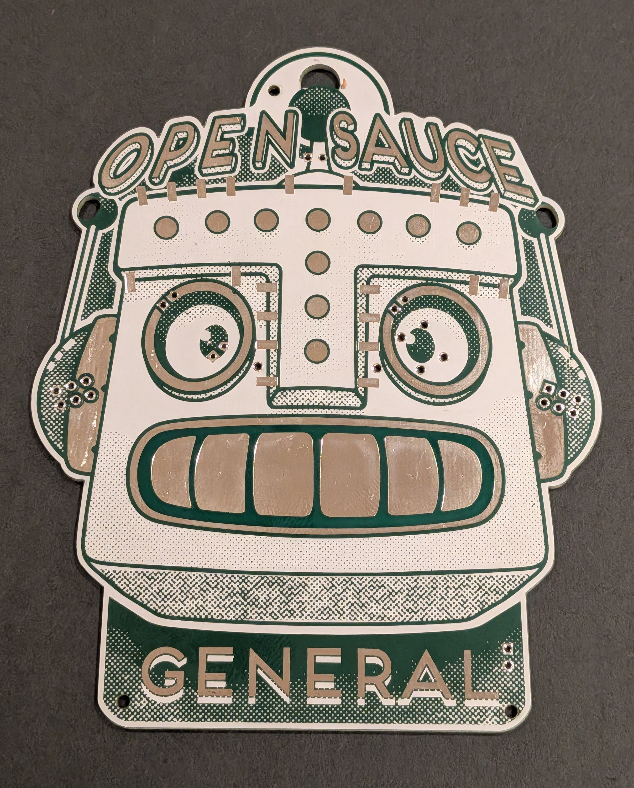
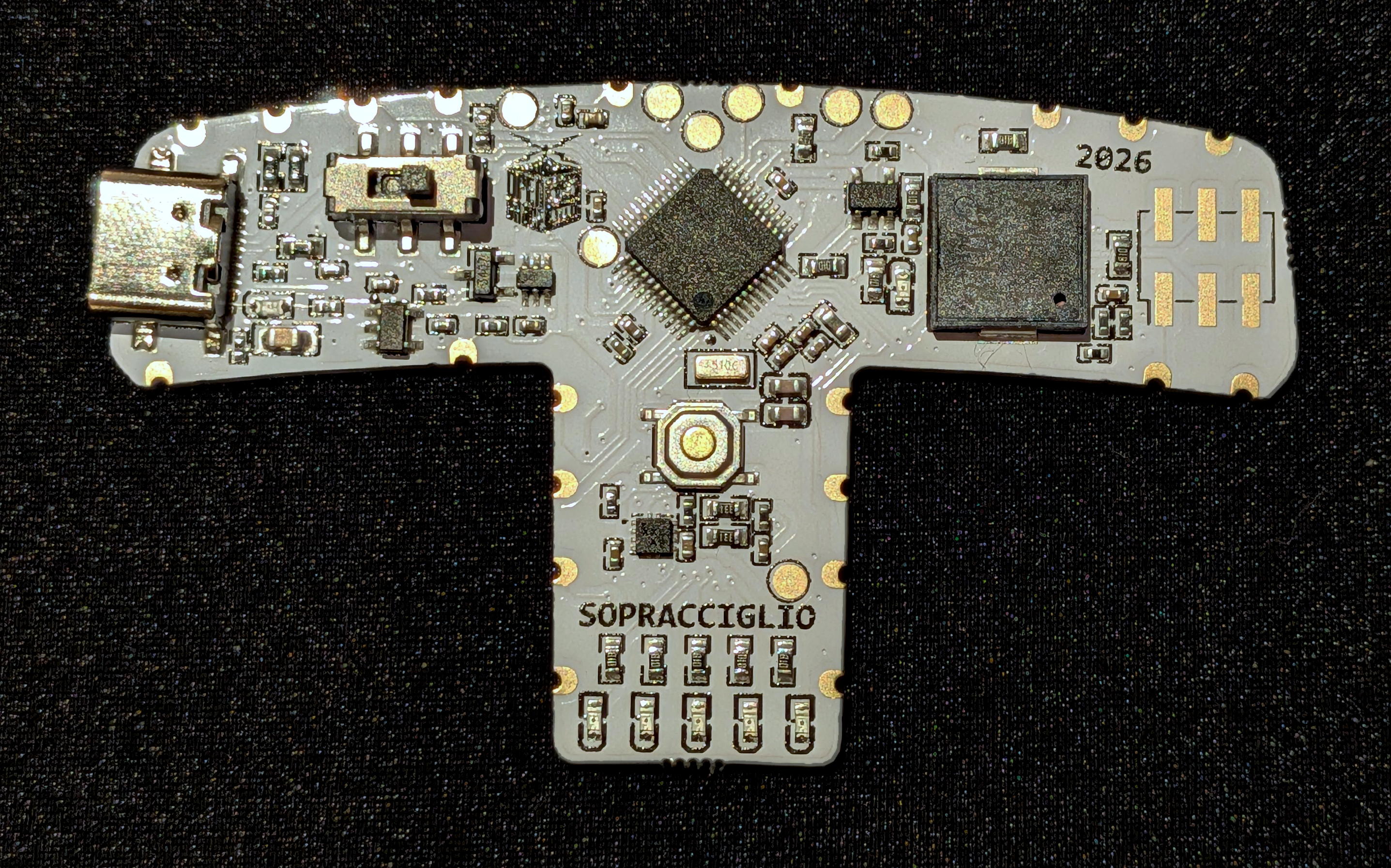
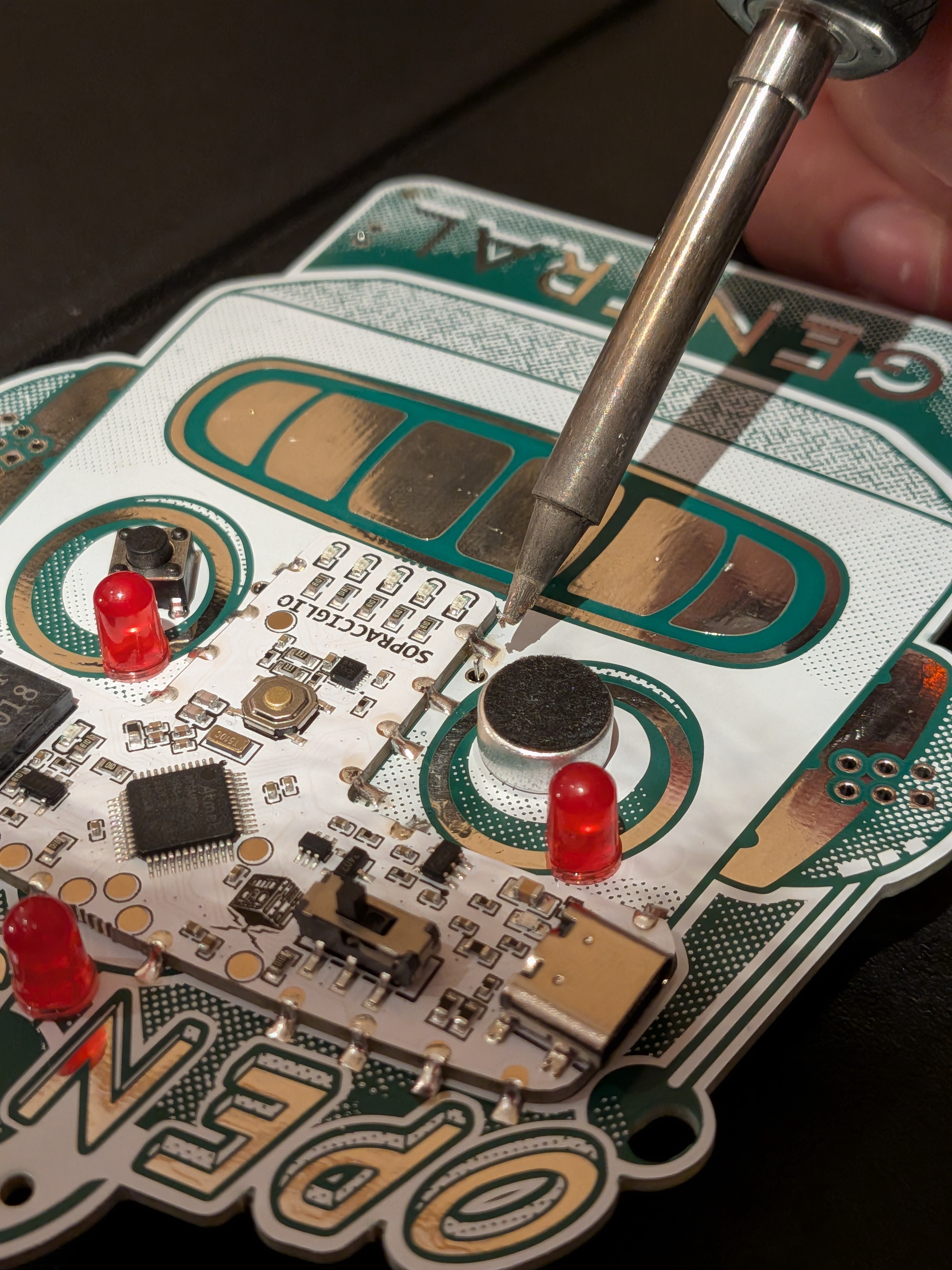
Carefully Align the T-Piece, checking that the gold pads on the edges are over the silver pads on the badge.
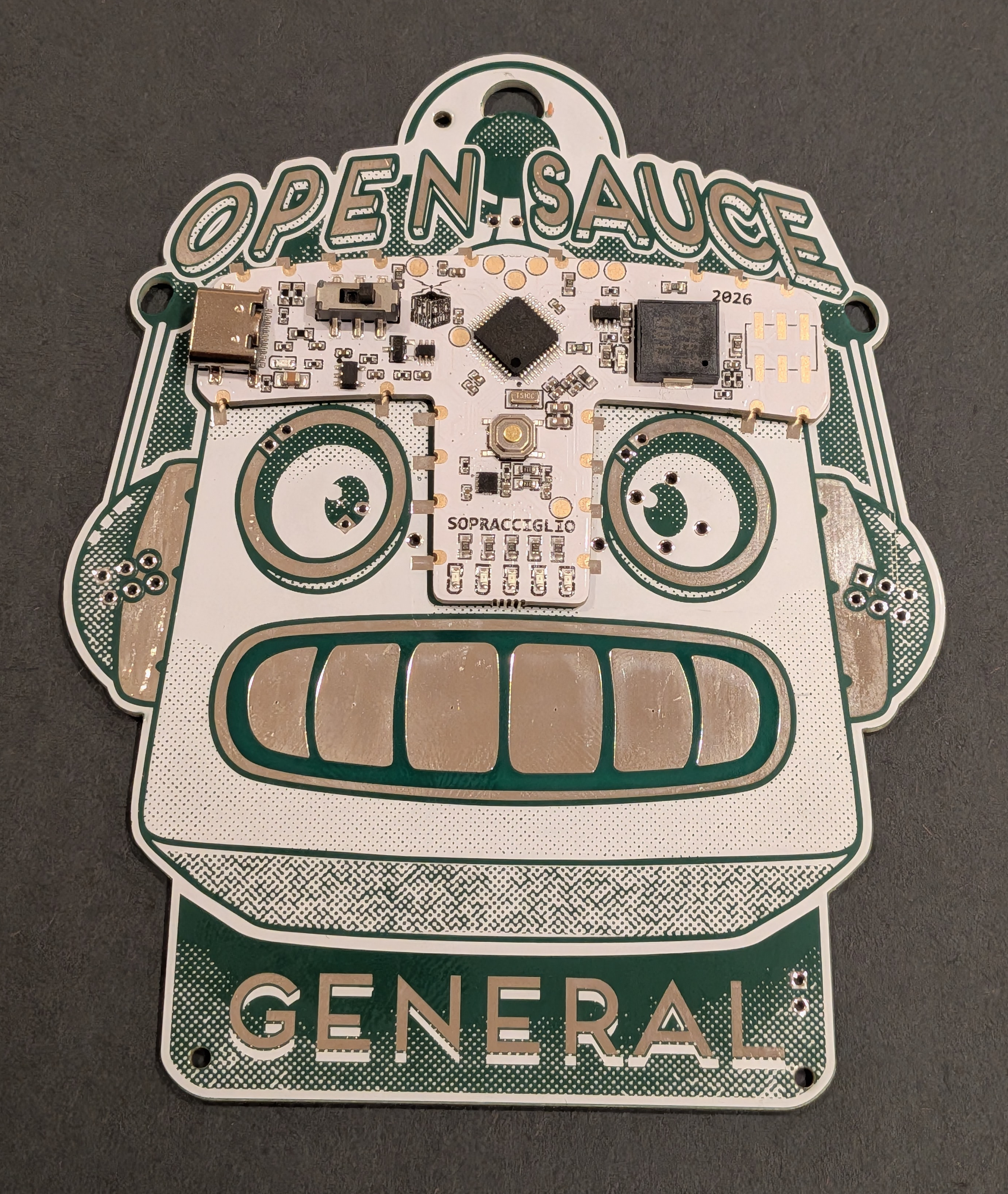
Solder the T-Piece to the badge. Make sure you get all 21 pads. We recommend soldering in this order:
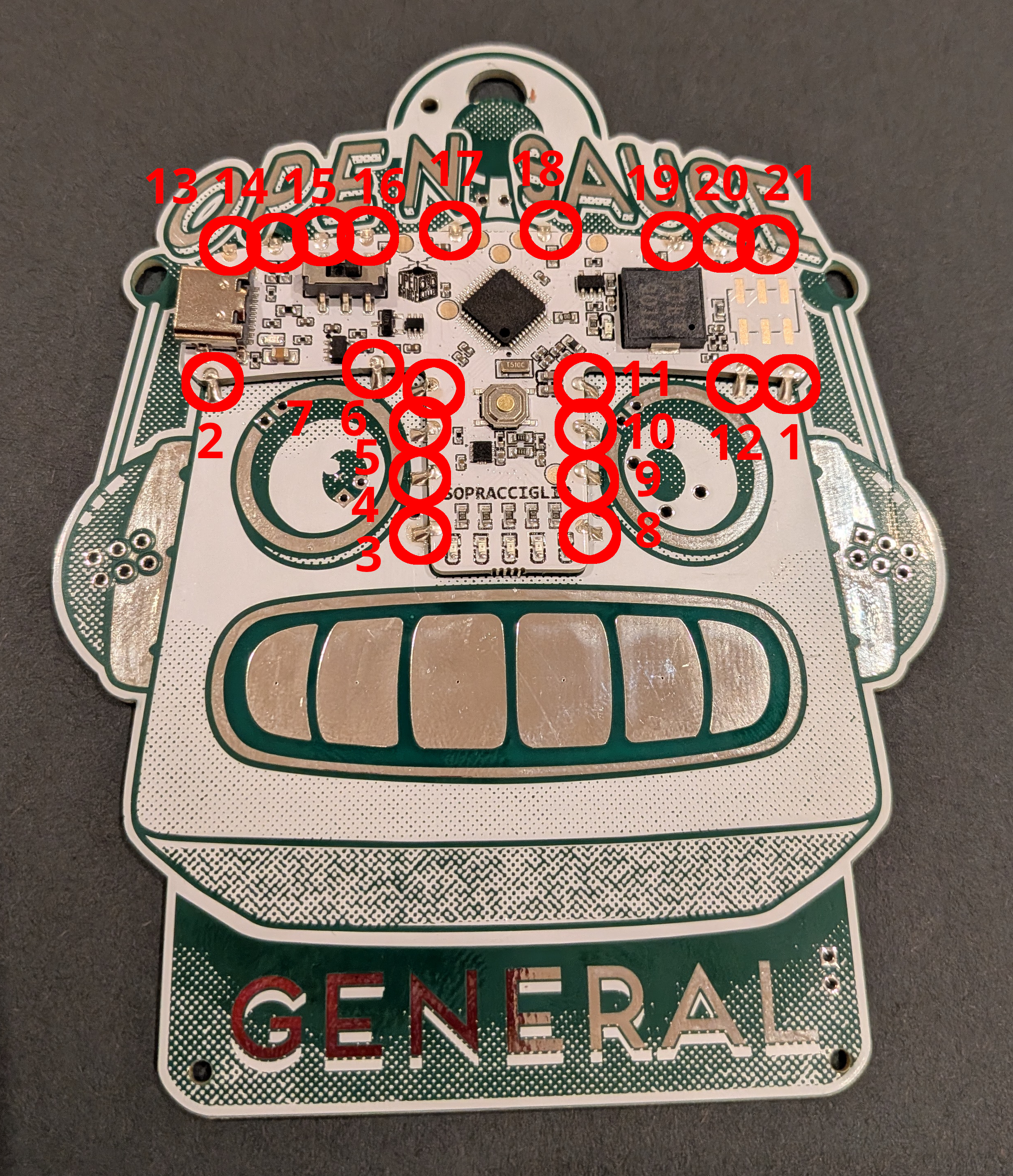
You may have to hold the T-Piece in place while you do the first joint or two. A friend could help hold it down. You want to completely fill the cutout on the edge of the T-Piece with solder and shoudl have a nice slope down to the badge pad.
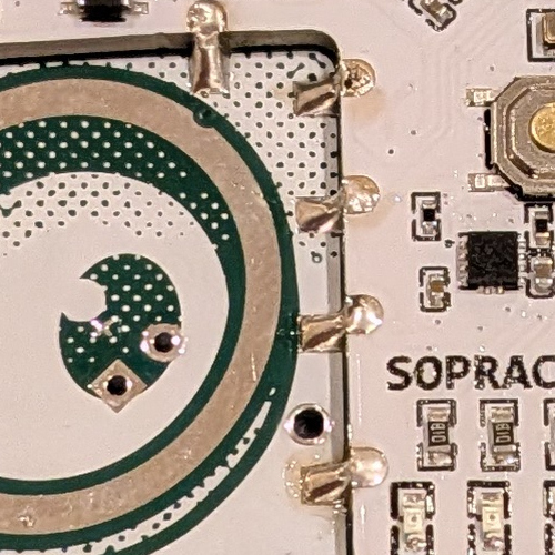
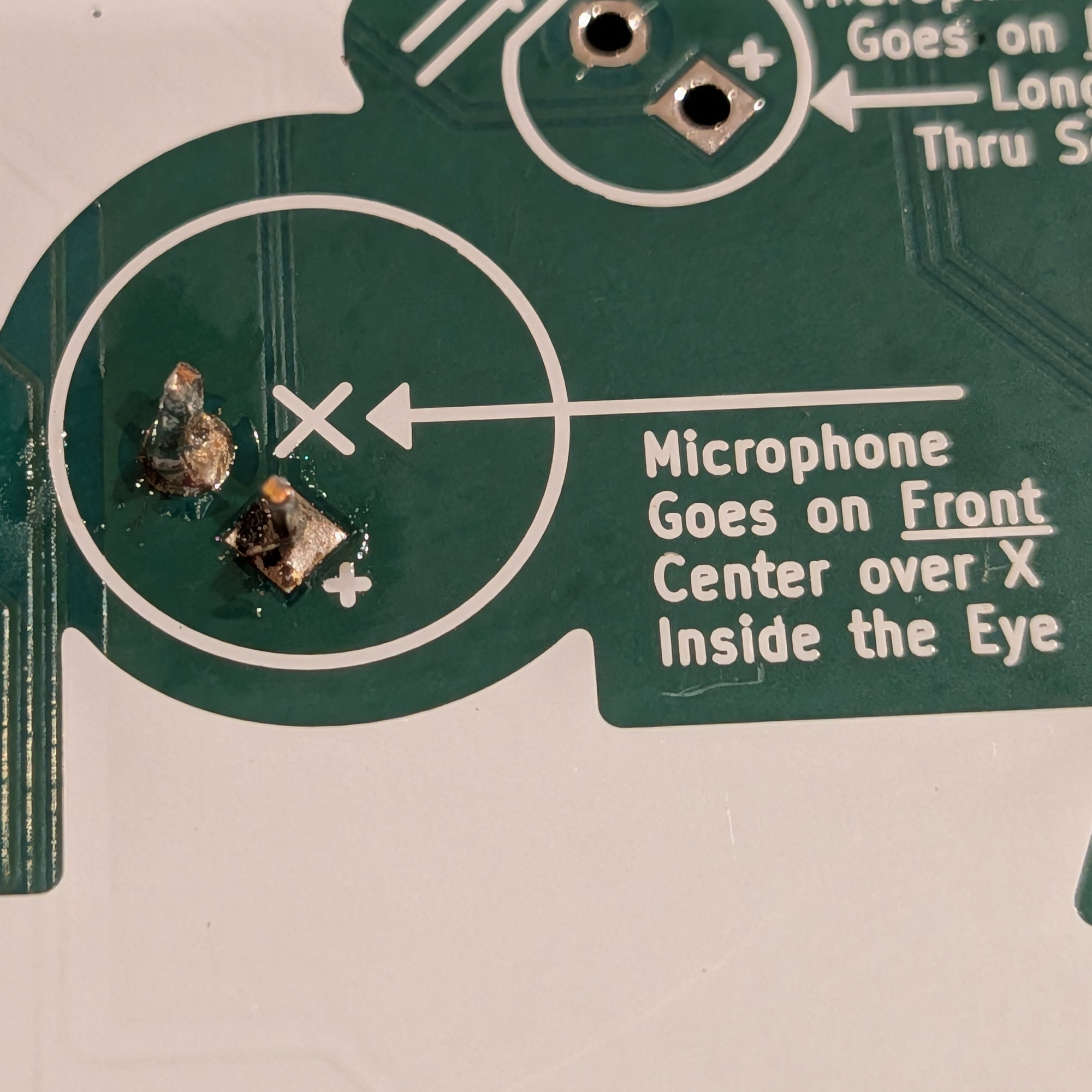
The microphone goes over SauceBot's right eye. Put it in from the face side, and make sure to get it centered over the pupil.
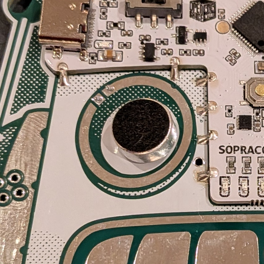
Carefully turn the badge over while keeping the microphone tight agianst the badge. The leads should come out both holes.
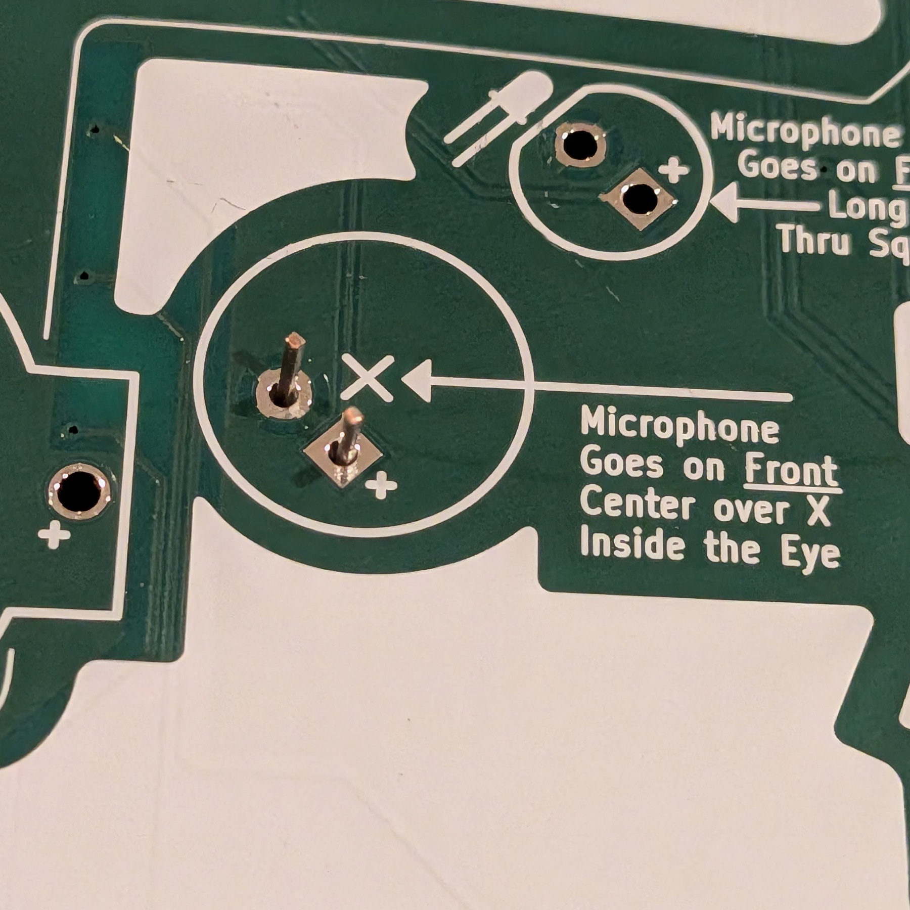
Solder the microphone leads.
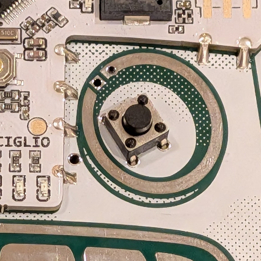
The button goes over SauceBot's left eye. Put it in from the face side, and make sure it's aligned with the holes. It will take a bit of force to push down flat agianst the badge.
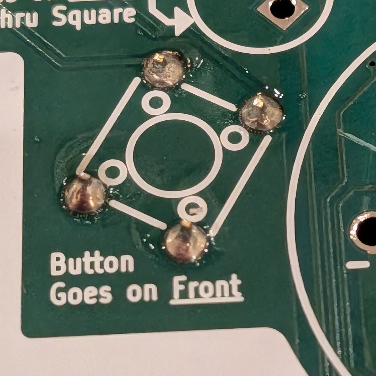
Turn the badge over while keeping the button in place. All 4 leads should stick out slightly from the badge. Solder all 4 leads of the button
The 3 LEDs are inserted from the front. Insert them so that the LONGER LEG goes in the SQUARE HOLE.
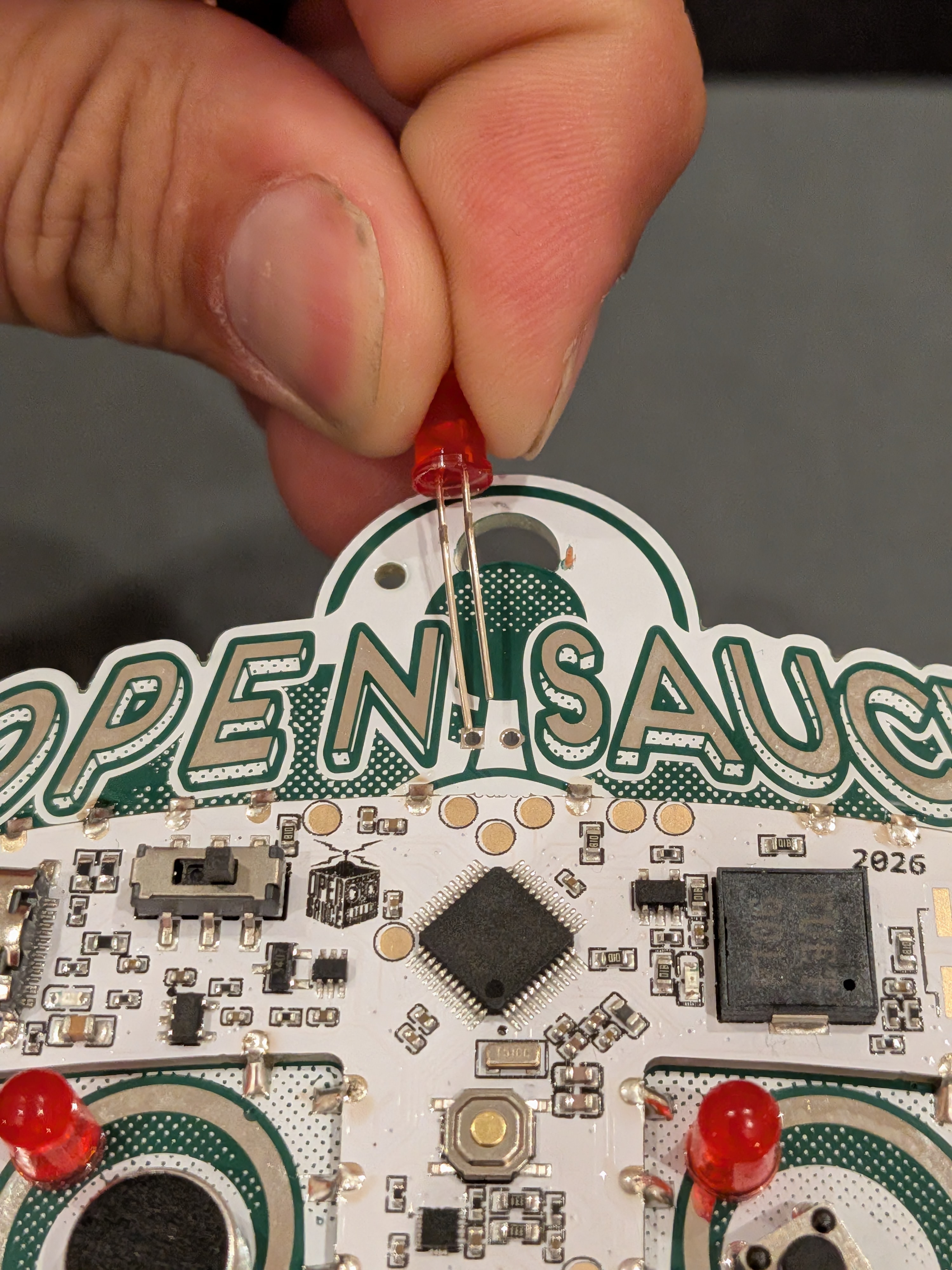
You can do each LED one at a time, or you can do all 3 at once, depending on how comfortable you are soldering.
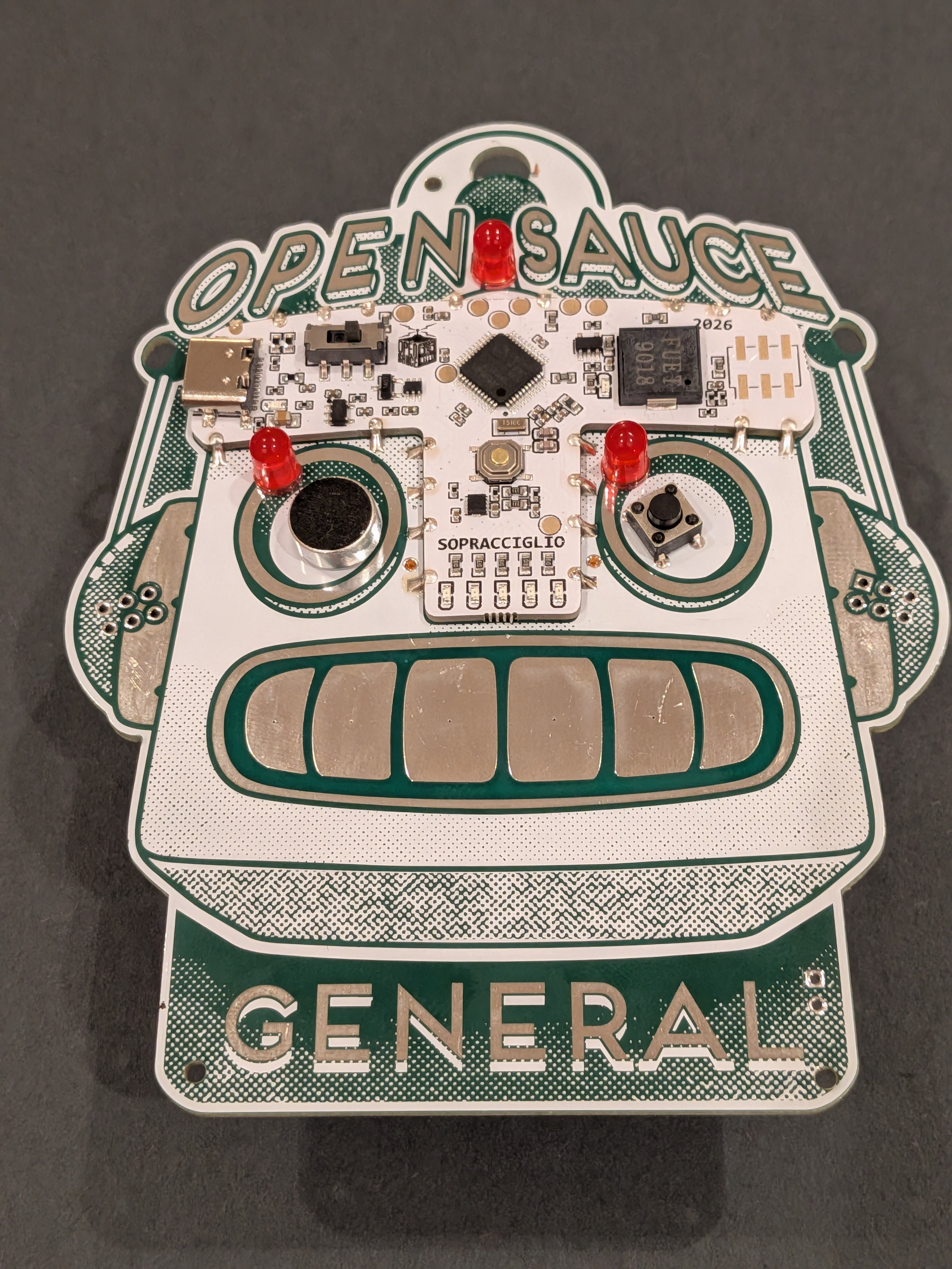
You might find it helps to bend the leads outward some to hold the LED in place while soldering.
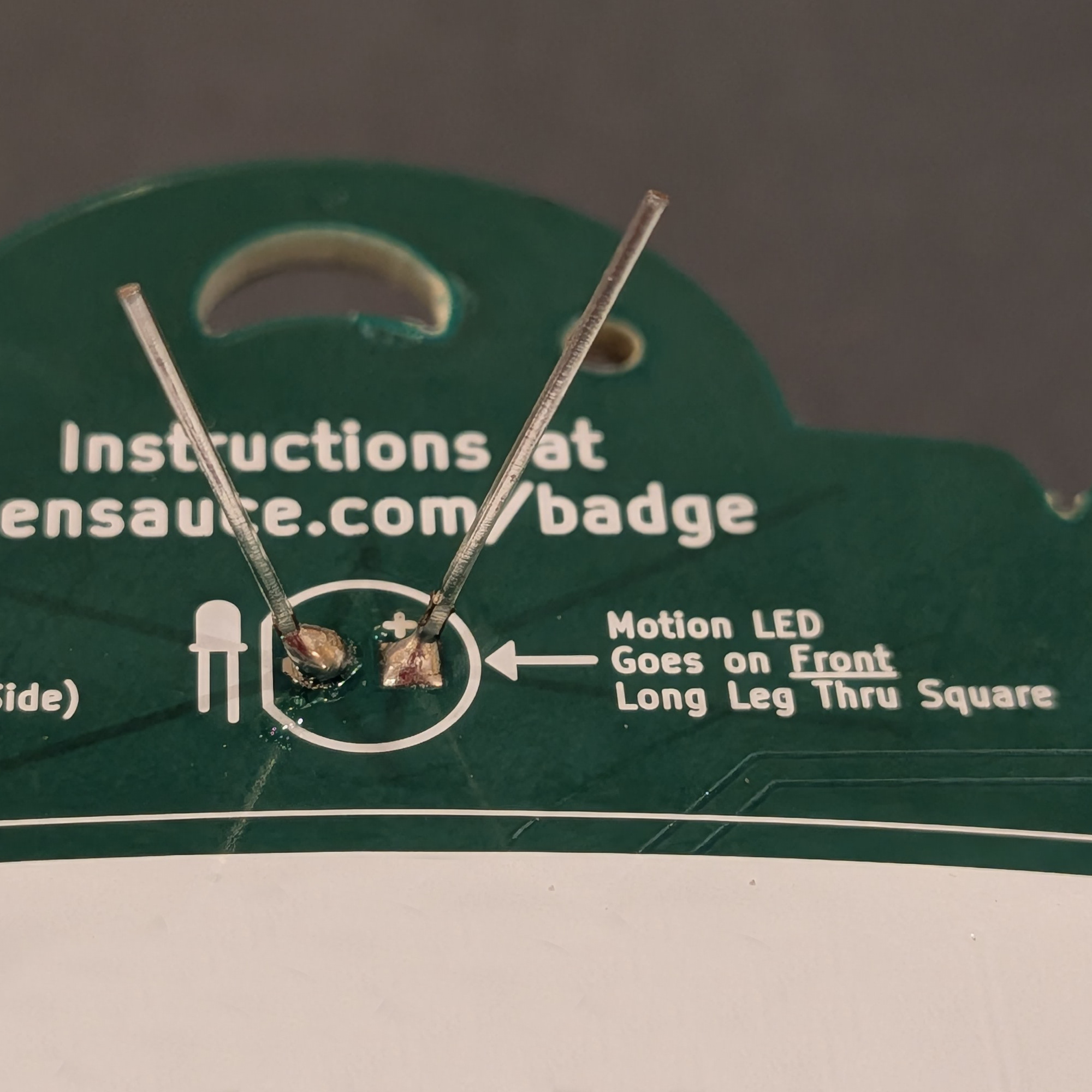
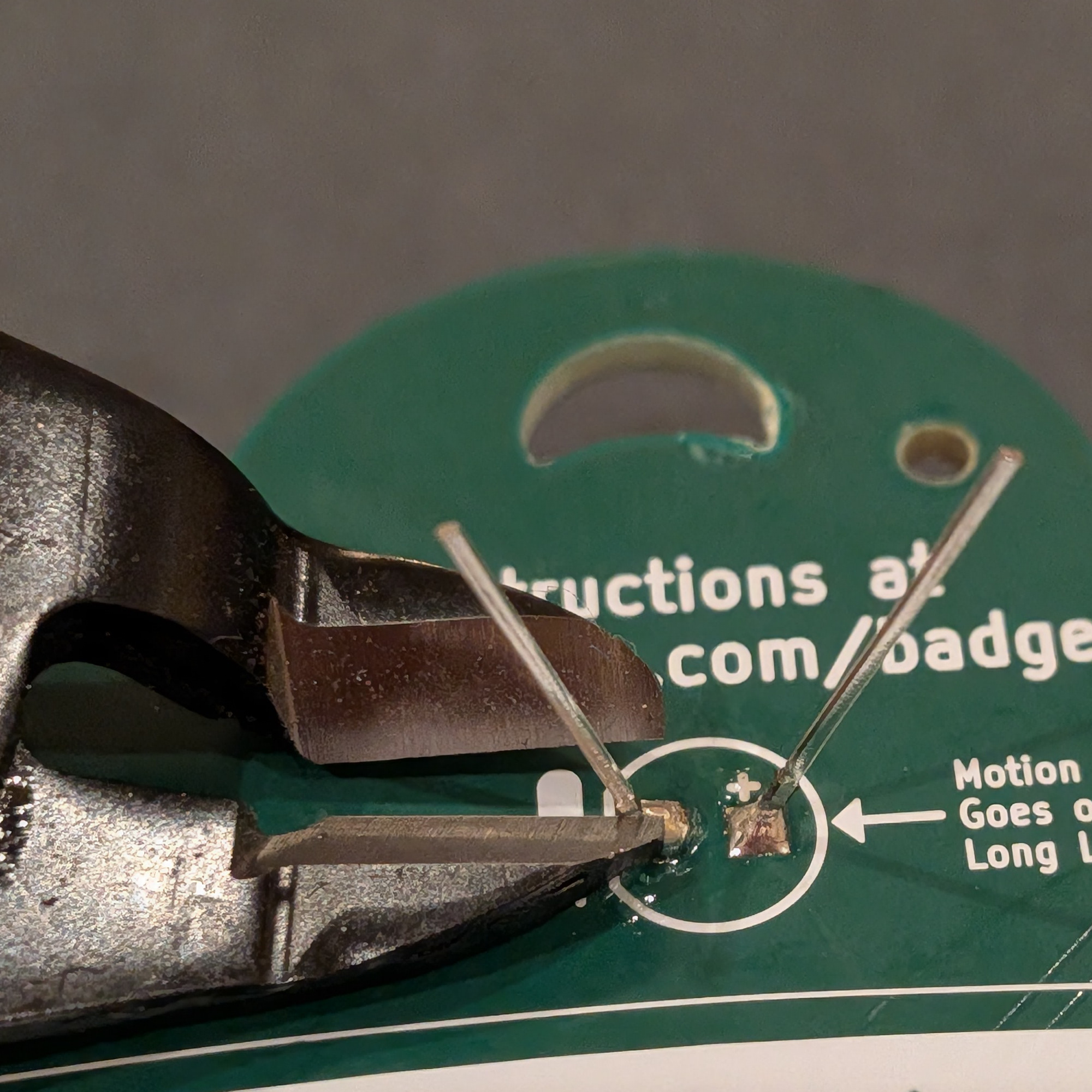
After you have soldered all 3 LEDs you can clip off the excess lead length. Use flushcut pliers, being careful not to cut too close and damage the board.
The battery holder is installed on the BACK, so turn the badge over and place it the outline.
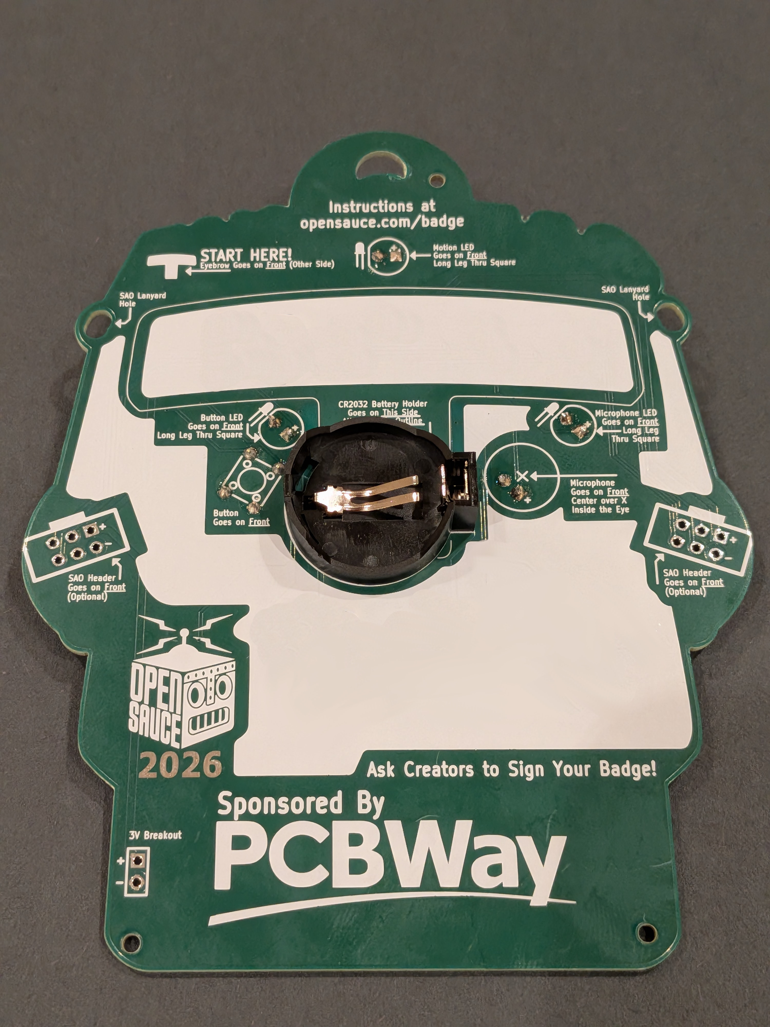
Flip your badge over to the front and solder the battery holder in. Be especially careful where you hold the iron. You don't want to melt any of your previous work.
Install the battery
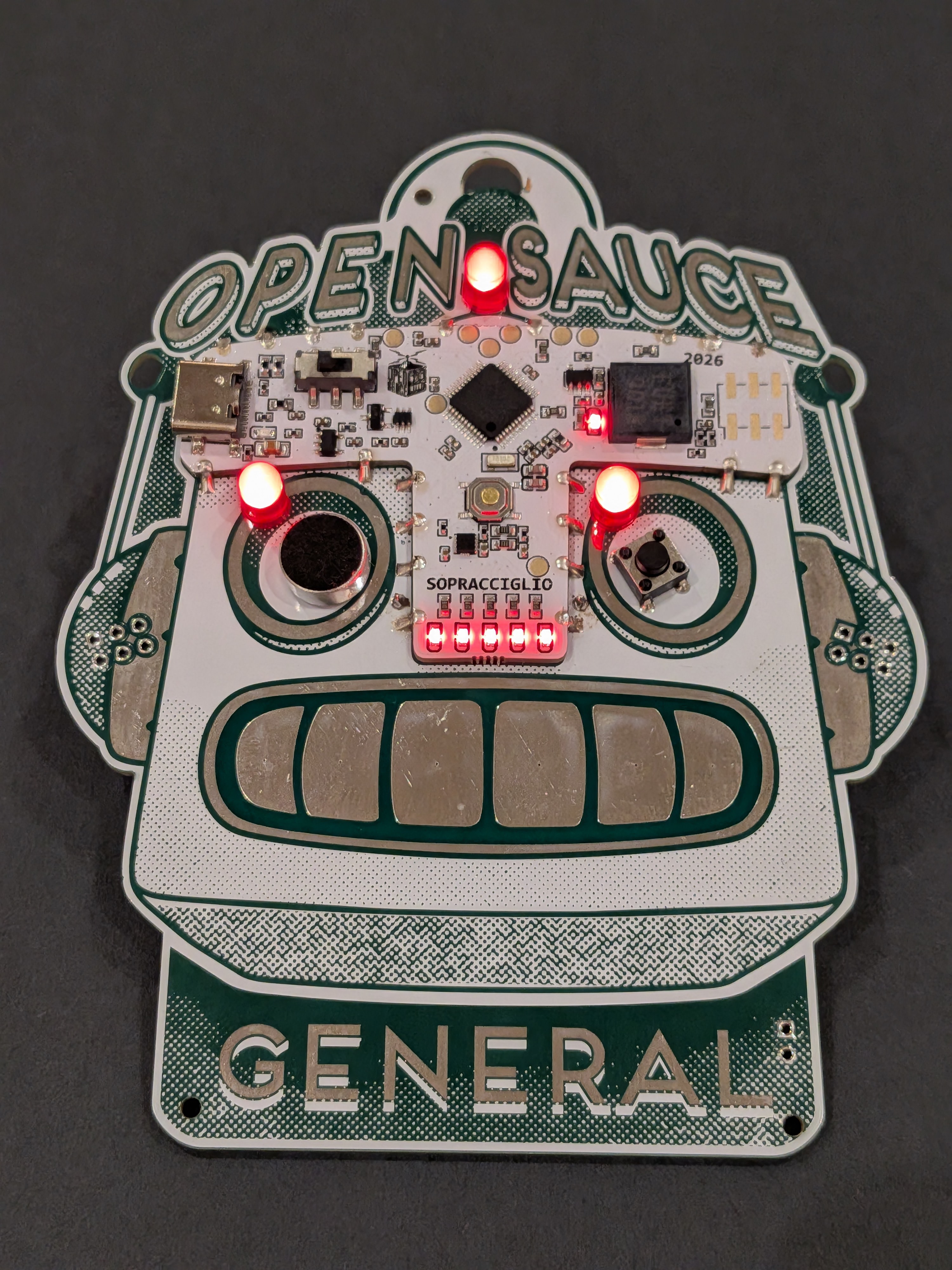
There are 2 6-pin headers on saucebot's ears for SAOs (Simple Add-Ons) you can add, as well as a 2-pin battery only add-on header. They are not requred to finsh your badge, but there are some cool things you can find at OpenSauce 2026 to plug in and augment your badge.
Your badge is also Arduino Compatible. We call it the Arduino Sopracciglio, but if you want to use it with Arduino IDE, you'll need to set your sketch up for an Arduino MKR Zero). You can also find the Code for the badge in Caleb Marting's GitHub.
Your Badge comes with a fun game to play! There are 5 actions that can be performed:
If you do the wrong action, or don't complete the action in time, it will let you know the game has ended and restart.
After 3 games that end with no user interaction, it the badge will go to sleep and leave the SAO ports powered on. There is a small LED that will flash every few seconds to let you know it's still alive. Press the mini reset button in the center of the T piece to wake it back up and start playing! If you don't want to waste power, turn the switch off (away from the USB port)
This code is a lot more complicated than it needs to be, I had higher aspirations than I ended up being able to accomplish at 3AM on Saturday of the event, so it's in a mostly unfinished state. I highly recommend trying the code in examples/putnamhack for a more flushed-out version.
| Qty | Value | Footprint | References |
|---|---|---|---|
| 11 | 0603WAF1001T5E | JLCImport:0603WAF1001T5E | R10, R17, R18, R19, R20, R21, R22, R23, R24, R25, R36 |
| 11 | CL05B104KO5NNNC | JLCImport:CL05B104KO5NNNC | C3, C4, C15, C18, C19, C22, C26, C27, C28, C29, C32 |
| 8 | 0402WGF5101TCE | JLCImport:0402WGF5101TCE | R5, R6, R7, R9, R14, R33, R34, R35 |
| 8 | TestPoint | TestPoint:TestPoint_Pad_D2.0mm | TP3, TP4, TP5, TP6, TP7, TP8, TP9, TP11 |
| 6 | KT-0603R | JLCImport:KT-0603R | LED2, LED4, LED5, LED6, LED7, LED8 |
| 4 | 0402WGF1002TCE | JLCImport:0402WGF1002TCE | R11, R15, R16, R38 |
| 3 | CG0603MLC-05E | JLCImport:CG0603MLC-05E | R1, R2, R3 |
| 3 | CL05A105KA5NQNC | JLCImport:CL05A105KA5NQNC | C20, C21, C30 |
| 3 | CL05A106MQ5NUNC | JLCImport:CL05A106MQ5NUNC | C2, C5, C6 |
| 2 | 0603WAF3300T5E | JLCImport:0603WAF3300T5E | R12, R13 |
| 2 | CL05A475MP5NRNC | JLCImport:CL05A475MP5NRNC | C23, C31 |
| 2 | CL10C200JB8NNNC | JLCImport:CL10C200JB8NNNC | C24, C25 |
| 1 | 0402WGF1004TCE | JLCImport:0402WGF1004TCE | R4 |
| 1 | 0603WAF1003T5E | JLCImport:0603WAF1003T5E | R37 |
| 1 | ABS07-32_768KHZ-7-T | JLCImport:ABS07-32_768KHZ-7-T | X3 |
| 1 | AO3407_C727158 | JLCImport:AO3407_C727158 | Q1 |
| 1 | ATSAMD21G18A-AU | JLCImport:ATSAMD21G18A-AU | U7 |
| 1 | BLM18PG471SN1D | JLCImport:BLM18PG471SN1D | L1 |
| 1 | Conn_02x03_Odd_Even | Connector_PinHeader_2.54mm:PinHeader_2x03_P2.54mm_Vertical_SMD | J1 |
| 1 | FST-9018 | JLCImport:FST-9018 | BUZZER1 |
| 1 | FV21X472K102ECG | JLCImport:FV21X472K102ECG | C1 |
| 1 | F_0603_00025_P2-0603G1TS2-06T-002 | JLCImport:F_0603_00025_P2-0603G1TS2-06T-002 | LED3 |
| 1 | LM66100DCKT | JLCImport:LM66100DCKT | U6 |
| 1 | MCP6001T-I_OT | JLCImport:MCP6001T-I_OT | U8 |
| 1 | ME6211C33M5G-N | JLCImport:ME6211C33M5G-N | LDO1 |
| 1 | MST22D18G2_125 | JLCImport:MST22D18G2_125 | SW3 |
| 1 | RC0402FR-0739RL | JLCImport:RC0402FR-0739RL | R8 |
| 1 | SC7A20HTR | JLCImport:SC7A20HTR | U2 |
| 1 | TS-1187A-B-A-B | JLCImport:TS-1187A-B-A-B | SW2 |
| 1 | TYPE-C_16P_QTWT | JLCImport:TYPE-C_16P_QTWT | USB1 |
| 1 | ~ | LayoutPads:T Piece | Castellated Pins1 |
calebmarting/os2026-badge
Schematics and firmware for the Open Sauce 2026 Badge and SAOs

calebmarting/os2026-badge
Schematics and firmware for the Open Sauce 2026 Badge and SAOs

calebmarting/os2026-badge
Schematics and firmware for the Open Sauce 2026 Badge and SAOs

calebmarting/os2026-badge
Schematics and firmware for the Open Sauce 2026 Badge and SAOs


EmperorMurfy/Fluid-Simulation-Pendant
A Fluid Simulation Pendant Inspired by Mitxela


Oscyloskop444/RGB-LED-matrix
Simple RGB led MATRIX with flexible size 10x10 - 20x20 based on WS2815F LEDs. It requires a power delivery adapter supporting 12v 2A minimum or direct 12v injection to the USB port to function.

mitra42/frugal-iot-hw-sensor
A simple, un-opinionated, multi-purpose sensor board, that can be wired to sensors using most common interfaces (I2C, ModBus, OneWire, Analog) with onboard charging and external antenna.

misko/prompt2device
The separate vNext PCB skill and orchestrator package is available alongside the reference workflow below; existing projects keep their accepted toolchain until an explicit migration.
It measures 69.8 × 40.4 mm and has 2 copper layers, 1.6 mm thick.
82 parts, built around the ATSAMD21G18A-AU, MCP6001T-I/OT(MS), SC7A20HTR and KT-0603R. The full list of its parts is on this page, with links to each part's symbol and footprint where PCBKit's library has them.
From the calebmarting/os2026-badge repository on GitHub, at the commit this page was made from: the board is Board Files/T Piece Kicad/T Piece Kicad.kicad_pcb and its schematic Board Files/Bop It Kicad/Bop It.kicad_sch. PCBKit opens the board in the browser, with nothing to install.
Its repository publishes it under the MIT licence: you may reuse it on that licence's terms (keep the author's notice, and for a copyleft licence share your changes alike).