2 layers60 × 62 mm
CPG
burgrp/bleriot-CPG
CPG is a mains-powered BleRiot node for controlling a circulation pump and a motorized 3-way or 4-way valve in floor-heating and radiator-heating circuits.
39 parts

 burgrp/bleriot-SSR5A
10 channel mains switch
SSR5A is an open-source printed circuit board by burgrp, from the burgrp/bleriot-SSR5A repository on GitHub. It is a 2-layer board of 150 × 48 mm with 66 parts on 63 nets, routed with 288 tracks and 145 vias.
It is built around the HLK-PM03, PAN2110P0AA and BTA08S-600CW(KTP), with the WS2812B among its other parts. Its parts include 27 resistors, 12 diodes, 8 ICs, 7 capacitors and 5 connectors.


SSR5A is a mains-powered five-channel BleRiot switch intended primarily for zone thermo-electric actuators in hydronic heating systems. Each independently controlled output switches mains line through a zero-cross optotriac and triac.
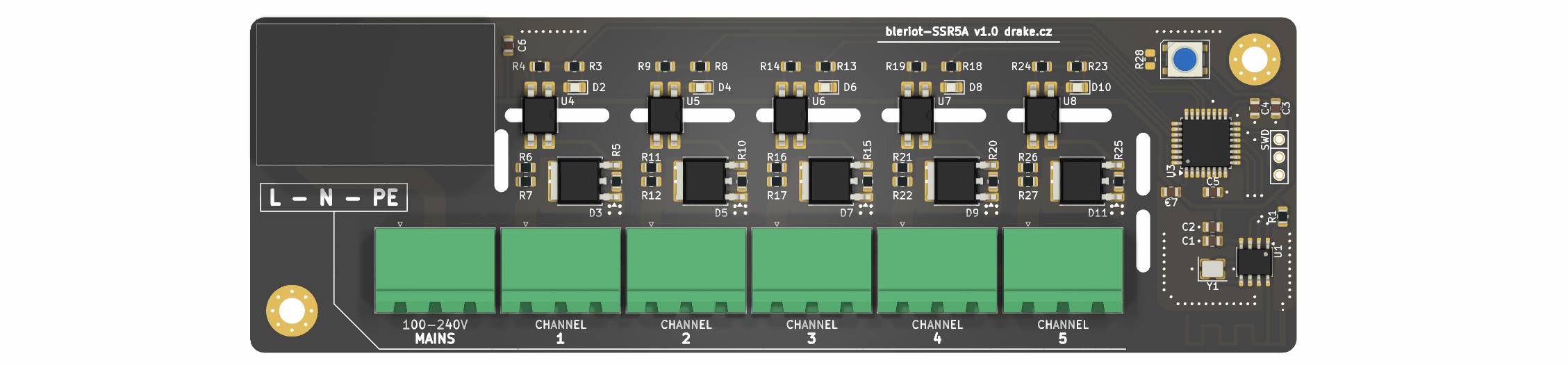
The board combines a PY32F030 microcontroller, PAN2110 radio, five output channels, a WS2812B status LED, and an isolated 3.3 V mains power supply. The outputs are on/off switches; they are not phase-angle dimmers.
Connector numbering follows the KiCad schematic.
| Connector | Pin 1 | Pin 2 | Pin 3 |
|---|---|---|---|
IN1 | Line (L) | Neutral (N) | Protective earth (PE) |
J1 | Channel 1 switched line | Neutral | Protective earth |
J2 | Channel 2 switched line | Neutral | Protective earth |
J3 | Channel 3 switched line | Neutral | Protective earth |
J4 | Channel 4 switched line | Neutral | Protective earth |
J5 | Channel 5 switched line | Neutral | Protective earth |
Each channel uses a MOC306x zero-cross optotriac and BTA08S-600CW triac. Its on-board indicator LED follows the output directly.
An enabled channel is exposed as a writable boolean register:
| Tag | Register |
|---|---|
| 1 | ssr.channel.1 |
| 2 | ssr.channel.2 |
| 3 | ssr.channel.3 |
| 4 | ssr.channel.4 |
| 5 | ssr.channel.5 |
Each channel has inventory-as-code configuration in
fw/cmd/dev/main.go:
Disabled omits the register and holds the physical output off.Inverted reverses the logical-to-physical output mapping.Default selects the logical value applied after power-on and RF link loss.Disabled takes precedence over inversion and the default. At startup, firmware first biases every active-low triac control inactive, then applies the configured defaults.
The node considers the BleRiot link offline after five seconds without a valid
packet. On the online-to-offline transition, it immediately restores every
channel to its configured logical Default and reapplies the corresponding
physical output level. This fail-safe also honors Inverted; for example, an
inverted channel with Default: false is physically energized while offline.
Choose defaults for the required safe state of the installation.
Stavová LED na PA6 zobrazuje spojení a logický stav kanálů. Od firmware
fw/v1.1.4 používá stejné oranžové barvy jako CPG:
| Stav | Indikace LED (RGB) |
|---|---|
| Online, všechny povolené kanály mají hodnotu false | Stálá oranžová 0xA05000 |
| Online, alespoň jeden povolený kanál má hodnotu true | Stálá zelená 0x104010 (beze změny) |
| Offline | Blikající oranžová 0xFF3000, 200 ms svítí a 800 ms nesvítí |
Aktivita se řídí logickou hodnotou registru bez ohledu na inverzi výstupu; zakázané kanály zelenou indikaci neaktivují. Offline indikace má přednost. Změna barev je ověřená testy a sestavením, nikoliv na fyzické LED.
The RF-loss behavior has been verified on hardware: channel 1 was commanded on, the hub was stopped, and its active-low MCU output returned inactive after the five-second link timeout. After reconnecting, all five registers reported their configured false defaults.
| Function | MCU pin |
|---|---|
| Channel 1 | PA11 |
| Channel 2 | PA12 |
| Channel 3 | PA15 |
| Channel 4 | PB3 |
| Channel 5 | PB4 |
| WS2812B data | PA6 |
| PAN2110 CSN | PA4 |
| PAN2110 SCK | PA5 |
| PAN2110 data | PA7 |
The importable ssr5a firmware exports Run and targets the py32f030x8
profile. Its device type owns the scheduler-none build policy and 100 kHz
attach-mode pyOCD settings. The local inventory bridges the radio node to a
Registry server. The SWD connector carries SWDIO, ground, and SWCLK but no reset
or target-voltage connection.
board/ contains the KiCad schematic, PCB, BOM, and fabrication
outputs.fw/ contains the importable TinyGo firmware, tests, and build profile.fw/spec/ contains configuration, the config-dependent register
table, chip, and firmware manifest.fw/cmd/dev/ contains the local inventory and BleRiot CLI.fw-orig/ contains the original MicroPython firmware for reference.sub/hw-kicad/ is the shared KiCad library submodule.Initialize the shared hardware library after cloning:
git submodule update --init --recursiveThe firmware requires Go, TinyGo with Puya target support, GNU Arm Embedded binutils, and pyOCD with the Puya CMSIS pack.
go -C fw test ./...
go -C fw run ./cmd/dev node gen --name ssr
go -C fw run ./cmd/dev node build --name ssr --disassembly
go -C fw run ./cmd/dev node build --name ssr --flash --rtt
With a Registry server running, start the local hub:
go -C fw run ./cmd/dev hub --registry http://localhost:8080 --diagnostics rfThis design connects directly to hazardous mains voltage. Assembly, installation, testing, and enclosure work must be performed by suitably qualified people using applicable electrical codes and safe isolation practices. Independently verify protection, creepage and clearance, protective earth continuity, enclosure construction, triac thermal limits, and actuator ratings before deployment.
Do not wire mains or an actuator from this README alone. Verify the assembled board against the schematic, PCB, and actuator manufacturer's documentation.
| Qty | Value | Footprint | References |
|---|---|---|---|
| 15 | 680R | Resistor_SMD:R_0805_2012Metric | R5, R6, R7, R10, R11, R12, R15, R16, R17, R20, R21, R22, R25, R26, R27 |
| 6 | 330R | Resistor_SMD:R_0805_2012Metric | R3, R8, R13, R18, R23, R28 |
| 6 | LED | LED_SMD:LED_0805_2012Metric_Pad1.15x1.40mm_HandSolder | D2, D4, D6, D8, D10, D13 |
| 5 | 270R | Resistor_SMD:R_0805_2012Metric | R4, R9, R14, R19, R24 |
| 5 | BTA08S-600CW | Package_TO_SOT_SMD:TO-252-2 | D3, D5, D7, D9, D11 |
| 5 | MOC306XMS | Package_DIP:SMDIP-4_W7.62mm | U4, U5, U6, U7, U8 |
| 4 | 100n | Capacitor_SMD:C_0805_2012Metric | C2, C4, C5, C7 |
| 2 | 1u | Capacitor_SMD:C_0805_2012Metric | C1, C3 |
| 2 | MountingHole | MountingHole:MountingHole_3.7mm_Pad_Via | H1, H2 |
| 1 | 1 | Connector_Phoenix_MSTB:PhoenixContact_MSTBA_2,5_3-G_1x03_P5.00mm_Horizontal | J1 |
| 1 | 10k | Resistor_SMD:R_0805_2012Metric | R1 |
| 1 | 16MHz | Crystal:Crystal_SMD_3225-4Pin_3.2x2.5mm | Y1 |
| 1 | 2 | Connector_Phoenix_MSTB:PhoenixContact_MSTBA_2,5_3-G_1x03_P5.00mm_Horizontal | J2 |
| 1 | 3 | Connector_Phoenix_MSTB:PhoenixContact_MSTBA_2,5_3-G_1x03_P5.00mm_Horizontal | J3 |
| 1 | 4 | Connector_Phoenix_MSTB:PhoenixContact_MSTBA_2,5_3-G_1x03_P5.00mm_Horizontal | J4 |
| 1 | 47u | Capacitor_SMD:C_0805_2012Metric | C6 |
| 1 | 5 | Connector_Phoenix_MSTB:PhoenixContact_MSTBA_2,5_3-G_1x03_P5.00mm_Horizontal | J5 |
| 1 | Antenna_Shield | RF_Antenna:Texas_SWRA117D_2.4GHz_Right | A1 |
| 1 | B72650M251K72 | Resistor_SMD:R_1210_3225Metric | RV1 |
| 1 | HLK-PM03 | Drake:HLK-PM01 | U2 |
| 1 | MAINS | Connector_Phoenix_MSTB:PhoenixContact_MSTBA_2,5_3-G_1x03_P5.00mm_Horizontal | IN1 |
| 1 | PAN2110P0AA | Package_SO:SOIC-8_3.9x4.9mm_P1.27mm | U1 |
| 1 | PY32F030K1xTx | Package_QFP:LQFP-32_7x7mm_P0.8mm | U3 |
| 1 | SWD | Drake:SWD | X1 |
| 1 | WS2812B | LED_SMD:LED_WS2812B_PLCC4_5.0x5.0mm_P3.2mm | D12 |
burgrp/bleriot-CPG
CPG is a mains-powered BleRiot node for controlling a circulation pump and a motorized 3-way or 4-way valve in floor-heating and radiator-heating circuits.


burgrp/bleriot-REG6
REG6 is a six-channel solid-state-relay controller built around a PY32F030 and PAN2110. This repository contains the KiCad hardware and a standalone TinyGo/BleRiot module under fw/ that exposes one integer percentage…


burgrp/bleriot
BleRiot is a compact request/response protocol for reading and writing named integer registers on low-power RF nodes. A Linux hub polls the nodes and bridges their registers to an external Registry service.

burgrp/bleriot-sense
BleRiot Sense is a compact single-sensor BleRiot node built around a PY32F003L16S6TU microcontroller and a PAN2110 long-range 2.4 GHz radio. Its sensor input is configured at assembly time for one of four uses:

It measures 150 × 48 mm and has 2 copper layers, 1.6 mm thick.
66 parts, built around the HLK-PM03, PAN2110P0AA, BTA08S-600CW(KTP) and WS2812B. The full list of its parts is on this page, with links to each part's symbol and footprint where PCBKit's library has them.
From the burgrp/bleriot-SSR5A repository on GitHub, at the commit this page was made from: the board is board/SSR5A.kicad_pcb and its schematic board/SSR5A.kicad_sch. PCBKit opens the board in the browser, with nothing to install.
Its repository states no licence, so its author keeps all rights: ask burgrp before reusing the design.