2 layers100 × 50 mm

 burgrp/hw-fan-switch
12V DC Fan switch based on ESP8266
Fan switch is an open-source printed circuit board by burgrp, from the burgrp/hw-fan-switch repository on GitHub. It is a 2-layer board of 50 × 35 mm with 23 parts on 23 nets, routed with 91 tracks and 39 vias.
It is built around the PAN2110P0AA, LM1117MP-3.3 and AO3400A, with the SK22 among its other parts. Its parts include 6 capacitors, 5 connectors, 3 resistors, 3 ICs and 2 diodes.


A small, wirelessly-controlled 12 V DC fan switch. It drives a fan with a variable PWM duty cycle and is controlled over a BLE long-range radio link, making it part of the Bleriot node network.
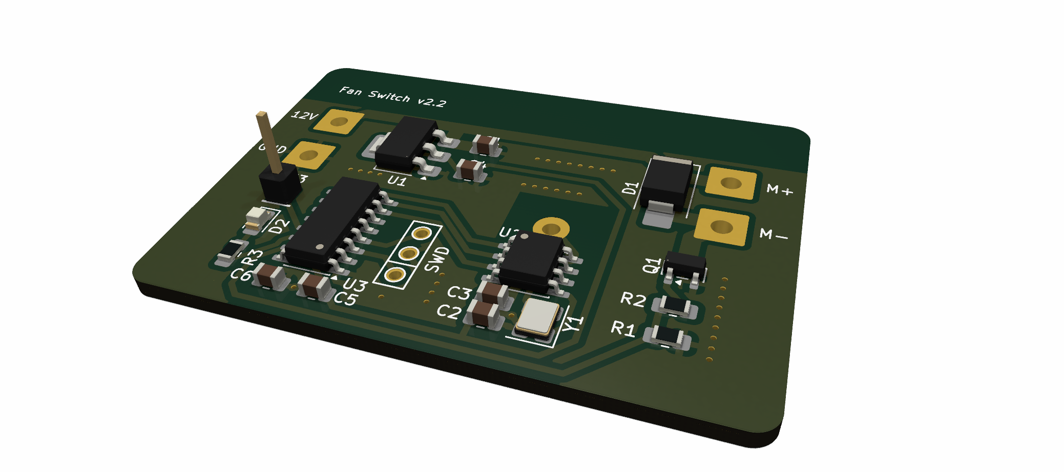
The board is built around a Puya PY32F003 Cortex-M0+ microcontroller with a PAN211x radio, and the firmware is written in Go and compiled with TinyGo.
PB1).| Path | Description |
|---|---|
board/ | KiCad hardware design (schematic, PCB, BOM, production files). |
fw/ | Importable TinyGo firmware and board-owned build profile. |
fw/spec/ | Device specification: registers and runtime Config. |
fw/cmd/dev/ | Optional local development inventory. |
sub/hw-kicad/ | Shared KiCad symbol/footprint library (git submodule). |
| Function | Pin |
|---|---|
| Yellow status LED | PB0 |
| Fan PWM output (TIM14_CH1, AF0) | PB1 |
| Radio SPI clock | PA2 |
| Radio SPI data | PA1 |
| Radio SPI chip select | PA4 |
The status LED is active high. A successfully decoded hub packet keeps the node online for five seconds. While online the LED remains on; after the timeout it follows BleRiot's 200 ms on, 800 ms off heartbeat until another packet arrives.
The KiCad project lives in board/, with fabrication outputs (Gerbers, BOM,
positions) under board/production/.
The firmware is the importable fanswitch package. Its TinyGo implementation
exports Run, while fw/spec exposes Config, the register table, chip, and a
typed build/flash profile. BleRiot generates a private external package main
inside the deployment module and calls Run with that instance's baked identity
and configuration. Nothing is generated in this repository for a deployment
build.
Clone with submodules:
git clone --recurse-submodules https://github.com/burgrp/hw-fan-switch.gitBuild deployment firmware from the authoritative site inventory. For the AGC
checkout and its basement.fan instance:
cd /home/paul/git/agc/bleriot

# Inspect the generated entry point without writing it
go run . node gen --name basement.fan

# One-time: install the target CMSIS pack
go run . node install-pack --name basement.fan

# Generate the private entry point and build image.elf
go run . node build --name basement.fan

# Generate, build, flash, and open RTT
go run . node build --name basement.fan --flash --rtt

# Open RTT without flashing
go run . node rtt --name basement.fan
The bleriot node commands resolve the selected inventory instance. node build generates its identity and Config under that deployment's private
.bleriot directory, then builds this module using the profile carried by
spec.Type. The deployment pins the firmware version in go.mod; it does not
carry fan-specific build flags. This repository's Makefile contains optional
aliases for fw/cmd/dev.
The inventory Config (see fw/spec/spec.go) controls runtime behaviour:
| Field | Meaning |
|---|---|
DefaultDuty | Fan duty cycle (0–100) applied at startup. |
LowDutyThreshold | Duty below which the fan is forced to 0. 0 disables the threshold. |
LowDutyKickstart | Duty briefly applied to spin up the fan from low speed. 0 disables the kickstart. |
The device exposes a single register over the Bleriot network:
| Register | Tag | Type | Unit | Description |
|---|---|---|---|---|
duty | 1 | int | % | PWM duty cycle, 0–100. |
Writing duty updates the fan speed; the hub's next scheduled GET observes the
new value. A NULL write stops the fan. Reading returns the current duty.
| Qty | Value | Footprint | References |
|---|---|---|---|
| 3 | 100n | Capacitor_SMD:C_0805_2012Metric | C3, C5, C6 |
| 2 | 10u | Capacitor_SMD:C_0805_2012Metric | C1, C4 |
| 1 | 100 | Resistor_SMD:R_0805_2012Metric_Pad1.20x1.40mm_HandSolder | R2 |
| 1 | 10k | Resistor_SMD:R_0805_2012Metric_Pad1.20x1.40mm_HandSolder | R1 |
| 1 | 12V | Connector_Wire:SolderWire-1sqmm_1x01_D1.4mm_OD3.9mm | J1 |
| 1 | 16MHz | Crystal:Crystal_SMD_3225-4Pin_3.2x2.5mm | Y1 |
| 1 | 1u | Capacitor_SMD:C_0805_2012Metric | C2 |
| 1 | 31mm | Drake:Wire antena 2.4GHz | A1 |
| 1 | 330R | Resistor_SMD:R_0805_2012Metric_Pad1.20x1.40mm_HandSolder | R3 |
| 1 | AO3400A | Package_TO_SOT_SMD:SOT-23 | Q1 |
| 1 | GND | Connector_Wire:SolderWire-1sqmm_1x01_D1.4mm_OD3.9mm | J2 |
| 1 | LED | LED_SMD:LED_0805_2012Metric_Pad1.15x1.40mm_HandSolder | D2 |
| 1 | LM1117MP-3.3 | Package_TO_SOT_SMD:SOT-223-3_TabPin2 | U1 |
| 1 | M+ | Connector_Wire:SolderWire-1sqmm_1x01_D1.4mm_OD3.9mm | J4 |
| 1 | M- | Connector_Wire:SolderWire-1sqmm_1x01_D1.4mm_OD3.9mm | J5 |
| 1 | PAN2110P0AA | Package_SO:SOIC-8_3.9x4.9mm_P1.27mm | U2 |
| 1 | PY32F003W1xSx | Package_SO:SOIC-16_3.9x9.9mm_P1.27mm | U3 |
| 1 | SK22 | Diode_SMD:D_SMB_Handsoldering | D1 |
| 1 | SWD | Drake:SWD | X1 |
| 1 | TX | Connector_PinHeader_2.54mm:PinHeader_1x01_P2.54mm_Vertical | J3 |


burgrp/bleriot
BleRiot is a compact request/response protocol for reading and writing named integer registers on low-power RF nodes. A Linux hub polls the nodes and bridges their registers to an external Registry service.

burgrp/bleriot-REG6
REG6 is a six-channel solid-state-relay controller built around a PY32F030 and PAN2110. This repository contains the KiCad hardware and a standalone TinyGo/BleRiot module under fw/ that exposes one integer percentage…


It measures 50 × 35 mm and has 2 copper layers, 1.6 mm thick.
23 parts, built around the PAN2110P0AA, LM1117MP-3.3, AO3400A and SK22. The full list of its parts is on this page, with links to each part's symbol and footprint where PCBKit's library has them.
From the burgrp/hw-fan-switch repository on GitHub, at the commit this page was made from: the board is board/fan-switch.kicad_pcb and its schematic board/fan-switch.kicad_sch. PCBKit opens the board in the browser, with nothing to install.
Its repository states no licence, so its author keeps all rights: ask burgrp before reusing the design.