

2 layers
Amplificador
nachocarballeda/gclass_amplifier
Diseño de un amplificador clase G para la materia Circuitos Electronicos 2. FIUBA
92 parts3
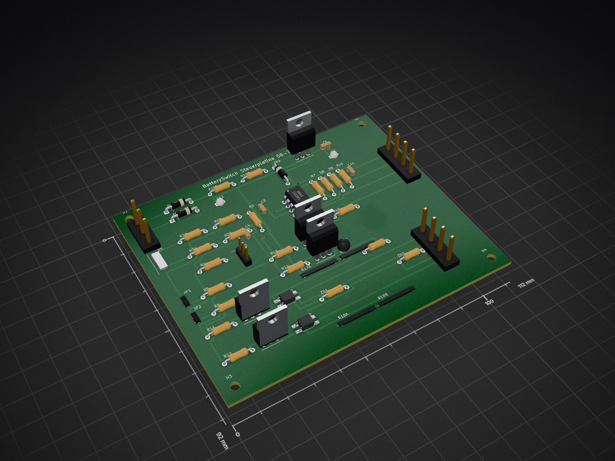
 bugtesterdani/BatterySwitch
Automatische Umschaltung zwischen zwei Akkus (Batterie 1: 50 Ah, Batterie 2: 30 Ah) in einem 72-V-System (ca. 71,x V Ladeschluss, ca. 58 V Entladeschluss — z. B.
BatterySwitch Steuerplatine is an open-source printed circuit board by bugtesterdani, from the bugtesterdani/BatterySwitch repository on GitHub. It is a 2-layer board of 112 × 92 mm with 56 parts on 39 nets, routed with 423 tracks and 12 vias.
It is built around the VOM1271, LM393 and BC547B, with the MPSA42 and MJE340 among its other parts. Its parts include 24 resistors, 6 capacitors, 4 diodes, 4 crystals and 1 IC.


Automatische Umschaltung zwischen zwei Akkus (Batterie 1: 50 Ah, Batterie 2: 30 Ah) in einem 72-V-System (ca. 71,x V Ladeschluss, ca. 58 V Entladeschluss — z. B. 17s-Li-Ion oder 20s-LiFePO4) durch direkten Vergleich der beiden Akkuspannungen (differentiell, keine feste Umschaltschwelle). Die Umschaltung erfolgt verschleißfrei über Leistungs-MOSFETs (ausgelegt für ca. 40 A Dauerstrom). Beide Umschalt-Offsets sind über je ein Potentiometer getrennt einstellbar.
U(Akku 1) < U(Akku 2) − Δ1 — Δ1 einstellbar mit Poti 1 (ca. 0,4 … 2,9 V).U(Akku 2) < U(Akku 1) − Δ2 — Δ2 einstellbar mit Poti 2 (unabhängig nachjustierbar).Δ1 + Δ2 (typisch 2 … 4 V) — die Schaltung schaltet selten, und der
Stützkondensator am Ausgang wird durch Umschalt-Totzeiten kaum belastet. BAT1 (50Ah, 72V) o──[Sicherung 50A/80VDC]──┤ MOSFET-Schalter S1 ├──┐
│ Sense ├──o LAST +
BAT2 (30Ah, 72V) o──[Sicherung 50A/80VDC]──┤ MOSFET-Schalter S2 ├──┘
│ Sense ▲
▼ │
Differenzkomparator (U1 ⇄ U2) ───────────────────────┘
Δ1-Poti · Δ2-Poti · Photovoltaik-Gate-Treiber · Break-before-make| Parameter | Wert |
|---|---|
| Systemspannung | 58 … 72 V DC |
| Dauerstrom | 40 A (Spitze kurzzeitig höher) |
| Schaltelemente | antiserielle N-Kanal-MOSFETs je Zweig (IRF100P219, TO-247, 100 V, ≤ 2 mΩ) |
| Verlustleistung bei 40 A | ca. 7 W je Zweig (1 Paar) bzw. 3,5 W (2 Paare parallel, empfohlen) → Kühlkörper |
| Gate-Ansteuerung | Photovoltaik-Treiber VOM1271 (potentialfrei, inhärent break-before-make) |
| Umschaltkriterium | Differenz U1 − U2 (kein fester Spannungswert) |
| Δ1 (auf Akku 2 schalten) | Poti 1, ca. 0,4 … 2,9 V |
| Δ2 (auf Akku 1 zurück) | Poti 2, ca. 0,4 … 2,9 V |
| Zusatzhysterese (fest) | ca. 0,1 … 0,8 V je Richtung |
| Umschalt-Totzeit | 5 … 10 ms (Akkus werden nie parallel geschaltet) |
| Eigenverbrauch Steuerung | ca. 25 mA (≈ 1,8 W, ≈ 0,6 Ah/Tag) |
| Dokument | Inhalt |
|---|---|
| hardware/BatterySwitch.kicad_sch | KiCad-Schaltplan (KiCad 6/7/8/9, direkt zu öffnen) — Vorschau: hardware/preview.svg |
| hardware/BatterySwitch_Steuerplatine.kicad_pcb | Platinenlayout Steuerplatine (112×92 mm, 2 Lagen, geroutet) — Vorschau: hardware/preview_pcb.svg |
| docs/schaltung.md | Vollständige Schaltungsbeschreibung, Schaltbilder, Dimensionierung und Formeln |
| docs/stueckliste.md | Stückliste (BOM) mit Bauteilwerten und Alternativen |
| docs/bestellliste.md | Bestellliste mit Händlern, Links und ca.-Preisen inkl. MwSt |
| docs/aufbau-und-abgleich.md | Aufbauhinweise, Verkabelung, Nullabgleich und Einstellen von Δ1/Δ2 |
| Qty | Value | Footprint | References |
|---|---|---|---|
| 4 | 27k 1% | bs:AXH | R1A, R1B, R3A, R3B |
| 4 | 3k3/1W | bs:AXH1W | R17A, R17B, R18A, R18B |
| 4 | M3 | bs:MH32 | H1, H2, H3, H4 |
| 3 | 100n | bs:RADV | C3, C4, C11 |
| 2 | 150k | bs:AXH | R5, R6 |
| 2 | 15V | bs:AXH | ZD1, ZD2 |
| 2 | 1N5819 | bs:DO41_AK | D1, D2 |
| 2 | 27k | bs:AXH | R11, R12 |
| 2 | 2k2 | bs:AXH | R15, R16 |
| 2 | 330k | bs:AXH | R13, R14 |
| 2 | 3k3 | bs:AXV | R7, R8 |
| 2 | 47k | bs:AXV | R9, R10 |
| 2 | 5k6/0,5W | bs:AXH | R19A, R19B |
| 2 | BC547B | bs:TO92_CBE | T3, T4 |
| 2 | MPSA42 | bs:TO92_EBC | T1, T2 |
| 2 | VOM1271 | bs:SOP4 | OC1, OC2 |
| 1 | 100n | bs:RAD | C2 |
| 1 | 100n/100V | bs:RAD | C12 |
| 1 | 100u/25V | bs:ELKO | C1 |
| 1 | 13V | bs:DO41V | ZD3 |
| 1 | 1k8 1% | bs:AXH | R4 |
| 1 | 2k0 1% | bs:AXV | R2 |
| 1 | 500R 25G | bs:TRIM | RV3 |
| 1 | Abgleich D1 | bs:HDR2 | JP1 |
| 1 | Abgleich D2 | bs:HDR2 | JP2 |
| 1 | Gates: G1 SK1 G2 SK2 | bs:TERM4 | X6 |
| 1 | LM393 | bs:DIP8 | U1 |
| 1 | MJE340 | bs:TO126_ECB | T5 |
| 1 | Potis: NJ2 OUT NK2 NOUT | bs:TERM4 | X7 |
| 1 | Sense: S1 S2 | bs:TERM2 | X5 |
| 1 | V+ Eingaenge: B1F B2F GND | bs:TERM3 | X4 |
| 1 | gelb | bs:LED3 | LED2 |
| 1 | gruen | bs:LED3 | LED1 |
nachocarballeda/gclass_amplifier
Diseño de un amplificador clase G para la materia Circuitos Electronicos 2. FIUBA

stancecoke/BionX_Minimal_Translator
Drive your BionX motor with a no-name battery and a Kunteng LCD-display without any further BionX-components


SSSound13/Cambridge_640A_PowerAmp
Replacement 4-layer KiCad PCB for the Cambridge Audio Azur 640A (V1) power amp board AP12707/6

It measures 112 × 92 mm and has 2 copper layers, 1.6 mm thick.
56 parts, built around the VOM1271, LM393, BC547B and MPSA42. The full list of its parts is on this page, with links to each part's symbol and footprint where PCBKit's library has them.
From the bugtesterdani/BatterySwitch repository on GitHub, at the commit this page was made from: the board is hardware/BatterySwitch_Steuerplatine.kicad_pcb and its schematic hardware/BatterySwitch.kicad_sch. PCBKit opens the board in the browser, with nothing to install.
Its repository states no licence, so its author keeps all rights: ask bugtesterdani before reusing the design.