
2 layers110 × 100 mm
STM32-LFR
bsce26023/STM32-LFR
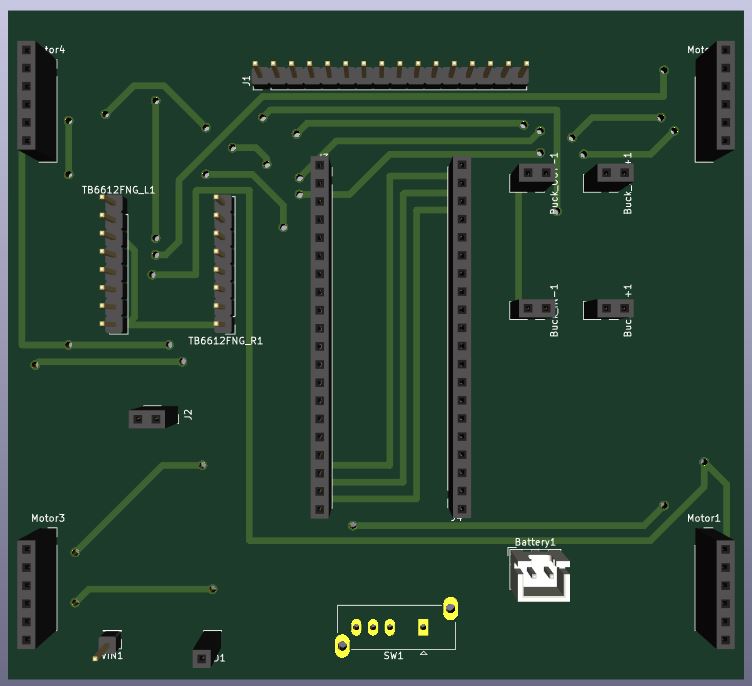
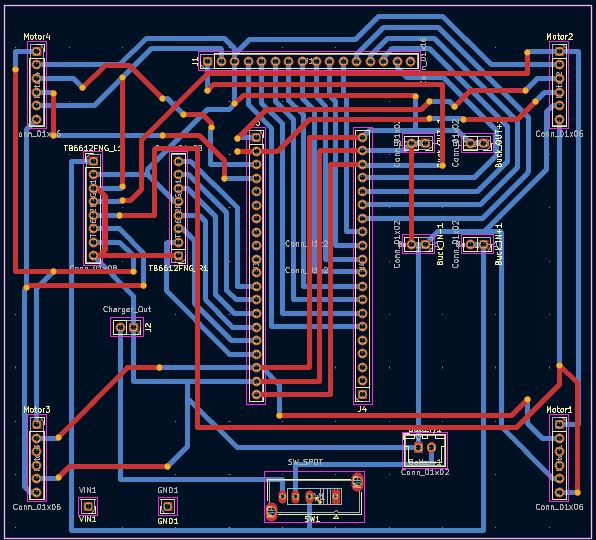
I designed a LFR from scratch including the PCBs for main board and a custom sensor array.
18 parts

 bsce26023/STM32-LFR
I designed a LFR from scratch including the PCBs for main board and a custom sensor array.
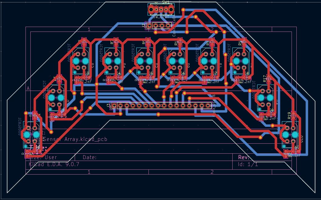
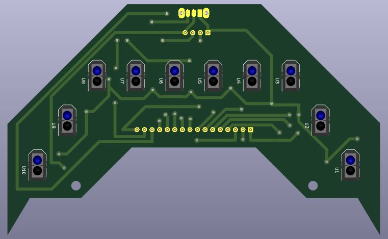
Sensor Array is an open-source printed circuit board by bsce26023, from the bsce26023/STM32-LFR repository on GitHub. It is a 2-layer board of 125 × 77.6 mm with 45 parts on 36 nets, routed with 336 tracks and 34 vias.
It is built around the TCRT5000. Its parts include 20 resistors, 10 capacitors, 10 ICs, 2 connectors and 1 switch. It belongs with the sensors and measurement boards of this library.
I designed a LFR from scratch including the PCBs for main board and a custom sensor array.
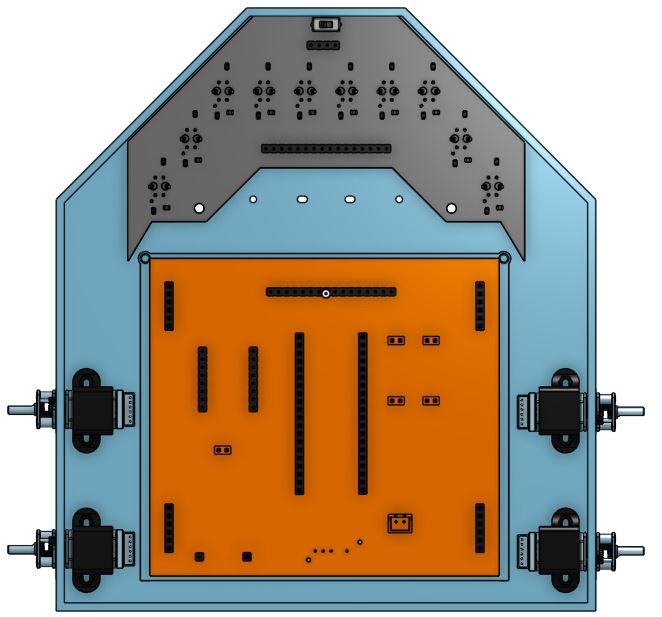 | 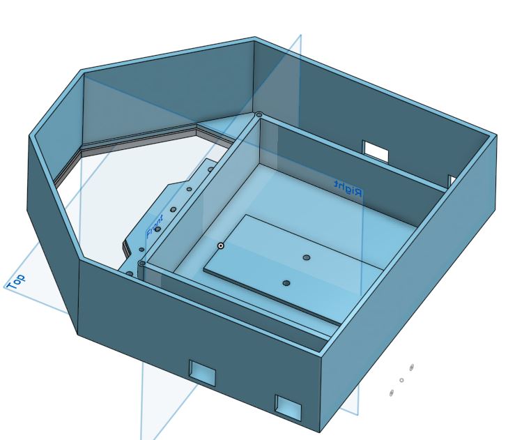 | 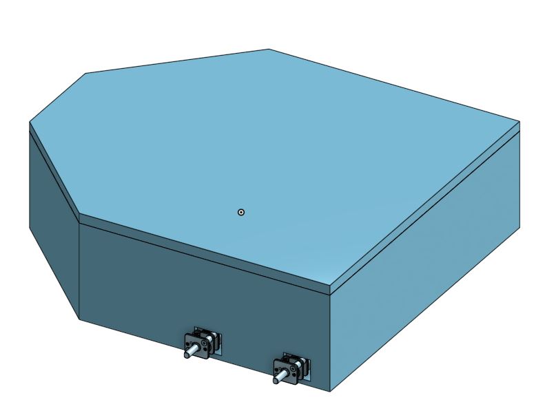 |
I've decided the components based on affordability, speed, availability and ease of use. Starting with the micro controller I've selected STM 32 BlackPill and for motors I've selected 3000rpm 6v N20 motors with encoders for fast speed to drive these motors I've chosen TB6612FNG motor driver because it has low voltage drop and also it is way lighter than L298N. I've decided to use a 2S Li-Po battery which is about 7.4v which can power the motors with ease and to power STM32 I'd use a step down buck converter to convert these 7.4v into 5v so we don't damage the STM32 to charge the battery I'd use a 2S charger and for the sensors I've designed a custom sensor array.
To talk about the connections, I'd Start with the Power connections. The battery provides 7.4v which goes to VMOT pin of motor driver and buck converter. the buck converter then outputs 5v which goes to VSYS on Pico. Now we have 3 voltages. i.e. 7.4v, 5v and 3.3v. now the 3.3v goes to VCC and STBY pin of TB6612FNG and VCC pin on Sensor Array.
Now lets talk about the Data and Logic Signals. The GPIO pins from 0 to 18 will be connected to sensor array and GPIO pins 19,20, 21, 22, 26, 27 will be connected to PWMA, AIN1, AIN2, PWMB, BIN1 and BIN2 respectively.
At the end the AO1, AO2 and BO1, BO2 will be connected to left and right motors respectively.
[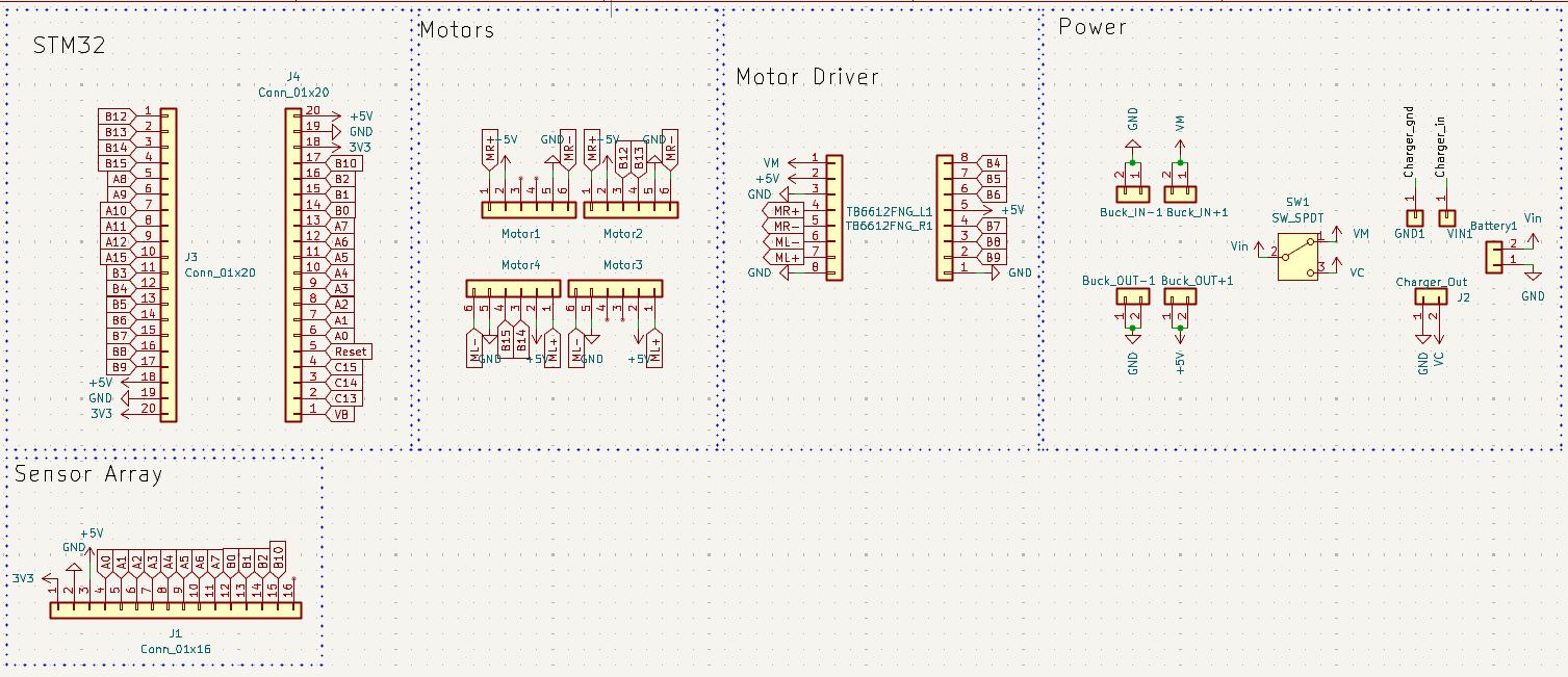 ]
| 3D Assembly | Tracks |
|---|---|
 |  |
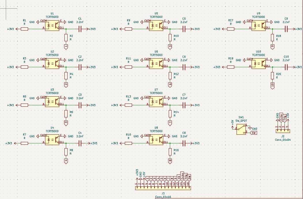
I designed the schematics for the sensor array, it is the working principle is inspired from the QTR-16RC sensor array.
| Schematics | Tracks |
|---|---|
 |  |
[ ]
| Name | Purpose | Quantity | Total Cost (USD) | Link | Distributor |
|---|---|---|---|---|---|
| PCB | PCB | 2 | 17 | https://cart.jlcpcb.com/shopcart/cart/ | JLCPCB |
| Mounting Brackets | Mounting motors | 1 | 3 | https://a.aliexpress.com/_c41oltrB | AliExpress |
| N20 Wheels | Wheels for Motors | 4 | 10 | https://a.aliexpress.com/_c3mDdjNx | Ali Express |
| Caster Wheels | Caster wheels | 2 | 4 | https://a.aliexpress.com/_c2yFCmMd | AliExpress |
| Slide Switch | Power Switch | 1 | 2 | https://a.aliexpress.com/_c3g6KmzX | AliExpress |
| TB6612FNG | Motor Driver | 1 | 4 | https://a.aliexpress.com/_c3bzgEgz | AliExpress |
| N20 Motors | Motors with Encoders | 4 | 25 | https://a.aliexpress.com/_c39Rykzn | AliExpress |
| Capacitor | Capacitance | 1 | 3 | https://a.aliexpress.com/_c3Ig4r1X | Aliexpress |
| Resistors | Resistance | 2 | 5 | https://a.aliexpress.com/_c3G1MsVL | Aliexpress |
| Limit switch | Bump sensor | 1 | 2.5 | https://a.aliexpress.com/_c3uz2Isv | Aliexpress |
| Ultrasonic sensor | Measures distance | 1 | 6 | https://a.aliexpress.com/_c35Zat1R | Aliexpress |
| TCRT5000 | Sensor | 1 | 7 | https://a.aliexpress.com/_c3RbgmiN | Aliexpress |
| Header pins | Soldering on pcb | 2 | 4 | https://a.aliexpress.com/_c4B0APx7 | Aliexpress |
| Mp1584 | Buck converter | 1 | 4.5 | https://a.aliexpress.com/_c4qnSguh | Aliexpress |
| Charging module | For charging battery | 1 | 2 | https://a.aliexpress.com/_c3Dtj3BL | Aliexpress |
| STM32 | Microcontroller | 1 | 6 | https://a.aliexpress.com/_c3GJD5FF | Aliexpress |
| Customs | - | - | 60 | - | AliExpress |
| Shipping | - | - | 19 | - | JLCPCB |
| Qty | Value | Footprint | References |
|---|---|---|---|
| 20 | R | Resistor_SMD:R_0805_2012Metric_Pad1.20x1.40mm_HandSolder | R1, R2, R3, R4, R5, R10, R11, R12, R13, R14, R15, R16, R17, R18, R19, R20 +4 |
| 10 | 2.2nF | Capacitor_SMD:C_0805_2012Metric_Pad1.18x1.45mm_HandSolder | C1, C2, C3, C4, C5, C6, C7, C8, C9, C10 |
| 10 | TCRT5000 | tcrt5000:tcrt5000 | U1, U2, U3, U4, U5, U6, U7, U8, U9, U10 |
| 1 | Conn_01x04 | Connector_PinHeader_2.54mm:PinHeader_1x04_P2.54mm_Vertical | J2 |
| 1 | Conn_01x16 | Connector_PinHeader_2.54mm:PinHeader_1x16_P2.54mm_Vertical | J3 |
| 1 | SW_SPDT | Button_Switch_THT:SW_Slide_SPDT_Straight_CK_OS102011MS2Q | SW1 |
The 43 most common of 45 parts.
It measures 125 × 77.6 mm and has 2 copper layers, 1.6 mm thick.
45 parts, built around the TCRT5000. The full list of its parts is on this page, with links to each part's symbol and footprint where PCBKit's library has them.
From the bsce26023/STM32-LFR repository on GitHub, at the commit this page was made from: the board is Custom Sensor Array/Sensor Array.kicad_pcb and its schematic Custom Sensor Array/Sensor Array.kicad_sch. PCBKit opens the board in the browser, with nothing to install.
Its repository states no licence, so its author keeps all rights: ask bsce26023 before reusing the design.
bsce26023/STM32-LFR
I designed a LFR from scratch including the PCBs for main board and a custom sensor array.

Squalius-cephalus/OpenRidingController
D.I.Y horse riding controller for the PC.


xtarke/automated_buggy
This shield connects microcontroller (MSP-EXP430FR2355) pins to the car's power board. Go to Power Board for more hardware information.

Amrlxyz/esp-lfr-buggy
2nd Year Embedded Systems Project (ESP) - Line Following Robot Buggy


ciiiutnfrc/eduromaa
Versión educativa del robot móvil RoMAA (EduRoMAA)

billtsol/Maze
This project demonstrates how to use an Arduino board, IR sensors, and a motor driver shield to create a maze-solving robot.

Potato-eater/Legacy2026
github repo for Robocup Junior Australia lightweight soccer team