Skip to the content
PCBKitNew board
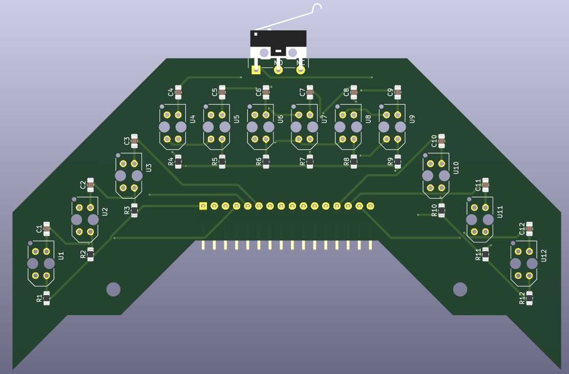
2 layers125 × 71 mmSensor Array, the printed circuit board in 3D

This repo is for a line following robot. I've designed this robot keeping in mind that this could be used in competitions. It is designed for high speed performance and complex line following

Size
125 × 71 mm
Copper layers
2
Thickness
1.6 mm
Parts
40
Nets
41
Pads
153
Tracks, vias
266, 24
Routed
Yes
KiCad
KiCad 9.0 (file 20241229)
Created
27 Feb 2026
Updated
24 Oct 2026

Overview

Sensor Array is an open-source printed circuit board by bsce26023, from the bsce26023/Line-Following-Robot repository on GitHub, published under the MIT licence. It is a 2-layer board of 125 × 71 mm with 40 parts on 41 nets, routed with 266 tracks and 24 vias.

It is built around the TCRT5000. Its parts include 12 capacitors, 12 resistors, 12 ICs and 1 connector. It belongs with the sensors and measurement and robots and motor control boards of this library.

Main components

1

README

README.md

Autonomous Line Following Robot

Hi! I wanted to make a Line Following Robot(LFR) and I visited some shops and online marketplaces but I couldn't find a good, fast, compact and accurate robot with a reasonable price. So, I created a LFR from scratch including the PCBs for main board and sensor array for the hardware part and code in 5 separate files. Now I will explain Components, Wiring, Coding, and sensor array separately.
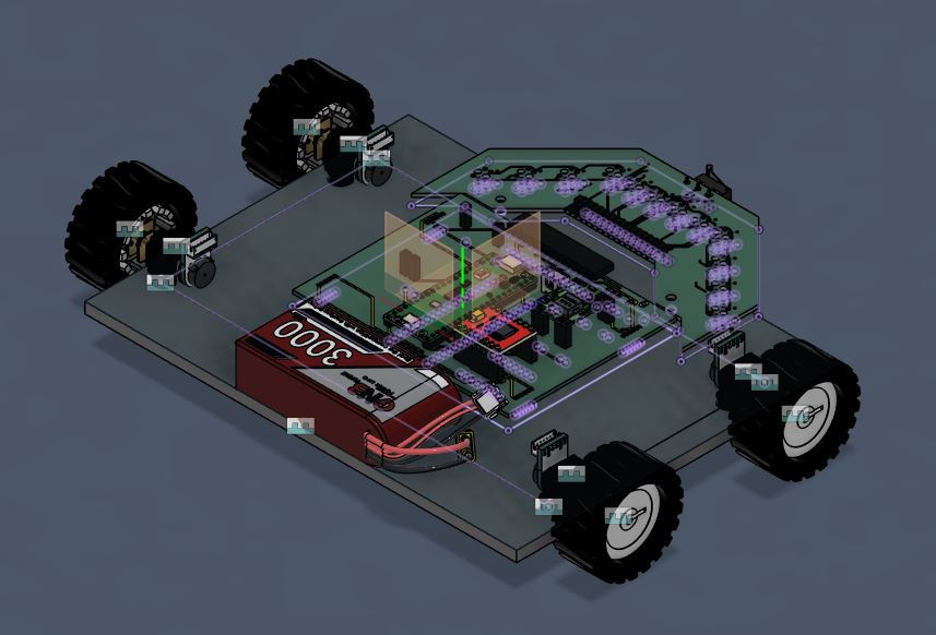
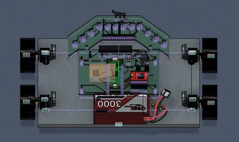
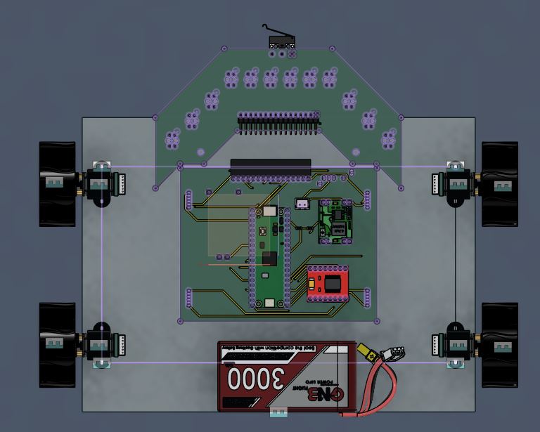
Corner_View

Top_viewBack_View

How to assemble and Opperate this LFR

1. Hardware Assembly : To Use this robot first you need to get the PCBs printed and then solder the components to them and then attach these to the chasis. Now plug and connect everything into its place and then you can move to software part.

2. Uploading the Code : Now connect Raspberry Pi Pico to your computer and open the LFR_Code.ino file and upload that to the Pico.

3. Tuning the Constants : Place the robot on a Black line with a White Background and adjust the Kp and Kd values such that the robot stops wobbling and runs smoothly.

4. Ready to Race : Now the robot is ready, You just need to turn it on and Race.

Components

I've decided the components based on affordability, speed, availability and ease of use. Starting with the micro controller I've selected Raspberry Pi Pico RP2040 because it has much more processing power than Arduino nano and I've not selected ESP 32 because I wanted to make the robot completely offline and autonomous and for motors I've selected 600rpm 6v N20 motors with encoders for fast speed and high torque to drive these motors I've chosen TB6612FNG motor driver because it has low voltage drop and also it is way lighter than L298N. I've used decided to use a 2S Li-Po battery which is about 7.4v which can power the motors with ease and to power Pico I'd use a step down buck converter to convert these 7.4v into 5v so we don't damage the Pico to charge the battery I'd use a 2S charger and for the sensors I've designed a custom sensor array.

PCB and Connections

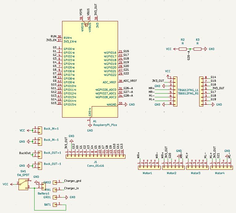
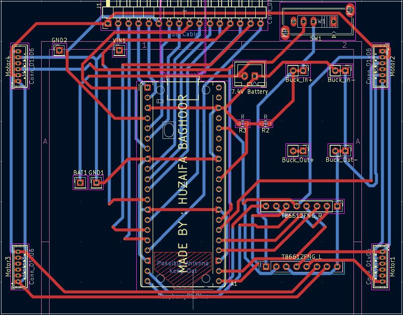
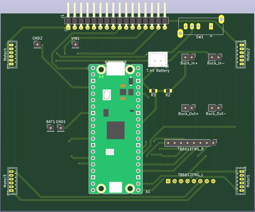
To talk about the connections, I'd Start with the Power connections. The battery provides 7.4v which goes to VMOT pin of motor driver and buck converter. the buck converter then outputs 5v which goes to VSYS on Pico. Now we have 3 voltages. i.e. 7.4v, 5v and 3.3v. now the 3.3v goes to VCC and STBY pin of TB6612FNG and VCC pin on Sensor Array. Now lets talk about the Data and Logic Signals. The GPIO pins from 0 to 18 will be connected to sensor array and GPIO pins 19,20, 21, 22, 26, 27 will be connected to PWMA, AIN1, AIN2, PWMB, BIN1 and BIN2 respectively. At the end the AO1, AO2 and BO1, BO2 will be connected to left and right motors respectively.

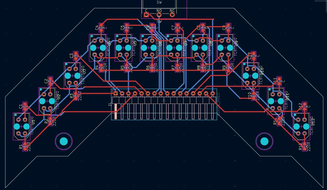
SchematicsTracks
schemeticsTracks

3D

Custom Built Sensor Array

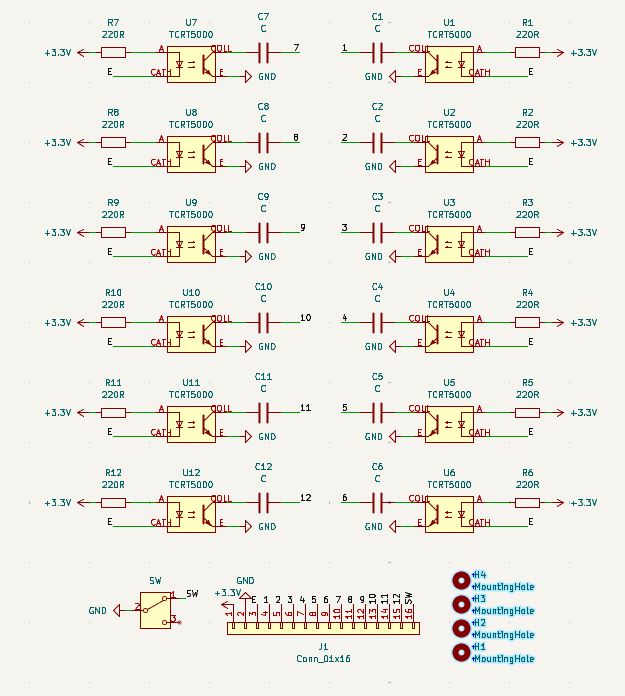
Now for the most difficult problem that I've faced in this project. I wanted to get analog sensor readings but Raspberry Pi Pico had only 3 analog pins. So I could add a Multiplexer chip which would make the PCB bulky. So I designed a workaround using an RC discharge Circuit. Instead of reading analog voltages, I paired 16 TCRT5000 sensors with 10nF capacitors and 220-Ohm Resistors. This converts the analog voltage signal to a digital timing signal. Working: The pico sends a brief signal to charge all 16 capacitors. Then it acts as a high-speed stopwatch to measure how fast each capacitors discharges.

  • If the sensor detects white surface, the capacitor discharges very fast
  • If the sensor detects black surface, the capacitor discharges slowly By doing this, I was able to read 16 analog sensors on 16 digital pins. To make the array even better, I also integrated two SPDT micro limit switch to use as bump sensors on left and right corners of the PCB.
SchematicsTracks
schemeticsTracks

3D

Bill of Materials (BOM)

After doing my research, the most affordable components I've got are as follows,

ComponentQuantityEst. Cost (USD)Purchase Links
Custom PCBs (JLCPCB)2 Sets$15.00https://jlcpcb.com/quote
Raspberry Pi Pico1$5.00https://ln.run/yanB3
TCRT5000 Transceivers16$4.00https://ln.run/hACwF
SMD Passives (0805)32$2.00https://ln.run/qddHJ
SPDT Limit Switches2$1.00https://ln.run/QSFtx
TB6612FNG Module1$3.00https://ln.run/ssqYa
6V N20 Motors (600 RPM)4$50.00https://ln.run/JM7nX
N20 Wheels & Brackets4$6.00https://ln.run/CkKDZ ---- https://ln.run/MqKmx
2S Battery (7.4V)1$3.00https://ln.run/iZsS-
Power Modules2$2.00https://ln.run/E-0I9 ---- https://ln.run/bBDg-
Misc. Hardware1$5.00N/A
Total Build Cost:~$96.00 USD

Because I designed the electronics to use standard, readily available modules, The robot is highly modular. If a motor driver or battery charger ever burns out during a competition, I can just unplug it and swap in a $3 replacement without having to desolder or rebuild the entire robot.

Parts

40
QtyValueFootprintReferences
12220RResistor_SMD:R_0805_2012Metric_Pad1.20x1.40mm_HandSolderR1, R2, R3, R4, R5, R6, R7, R8, R9, R10, R11, R12
12CCapacitor_SMD:C_0805_2012Metric_Pad1.18x1.45mm_HandSolderC1, C2, C3, C4, C5, C6, C7, C8, C9, C10, C11, C12
12TCRT5000tcrt5000:tcrt5000U1, U2, U3, U4, U5, U6, U7, U8, U9, U10, U11, U12
2MountingHoleMountingHole:MountingHole_3.2mm_M3H1, H2
1Conn_01x16Connector_PinHeader_2.54mm:PinHeader_1x16_P2.54mm_HorizontalJ1
1SWButton_Switch_THT:SW_XKB_DM1-16UC-1SW

Questions

How big is the Sensor Array PCB?

It measures 125 × 71 mm and has 2 copper layers, 1.6 mm thick.

What parts does the Sensor Array use?

40 parts, built around the TCRT5000. The full list of its parts is on this page, with links to each part's symbol and footprint where PCBKit's library has them.

Where can I download the Sensor Array KiCad files?

From the bsce26023/Line-Following-Robot repository on GitHub, at the commit this page was made from: the board is Sensor Array/Sensor Array.kicad_pcb and its schematic PCB/PCB.kicad_sch. PCBKit opens the board in the browser, with nothing to install.

Can I use the Sensor Array design in my own project?

Its repository publishes it under the MIT licence: you may reuse it on that licence's terms (keep the author's notice, and for a copyleft licence share your changes alike).

More from bsce26023/Line-Following-Robot

2
  • 2 layers100 × 78 mmLine Following Robot, the printed circuit board in 3D

    Line Following Robot

    bsce26023/Line-Following-Robot

    This repo is for a line following robot. I've designed this robot keeping in mind that this could be used in competitions. It is designed for high speed performance and complex line following

    20 partsMIT
  • 2 layers75 × 75 mmPCB (1), the printed circuit board in 3D

    PCB (1)

    bsce26023/Line-Following-Robot

    This repo is for a line following robot. I've designed this robot keeping in mind that this could be used in competitions. It is designed for high speed performance and complex line following

    14 partsMIT

Similar boards

  • 2 layers200 × 78.8 mmOpenridingcontroller rev2, the printed circuit board in 3D

    Openridingcontroller rev2

    Squalius-cephalus/OpenRidingController

    D.I.Y horse riding controller for the PC.

    30 parts13
  • 2 layers66.4 × 52.5 mmWatermeter v0.4, the printed circuit board in 3D

    Watermeter v0.4

    rbisschops/mySensors

    mySensors

    39 parts6
  • 2 layers135.8 × 56.1 mmPower board, the printed circuit board in 3D

    Power board

    xtarke/automated_buggy

    This shield connects microcontroller (MSP-EXP430FR2355) pins to the car's power board. Go to Power Board for more hardware information.

    87 parts5GPL-3.0
  • 2 layers160 × 42 mmESP kicad2, the printed circuit board in 3D

    ESP kicad2

    Amrlxyz/esp-lfr-buggy

    2nd Year Embedded Systems Project (ESP) - Line Following Robot Buggy

    28 parts4
  • 2 layers34.1 × 108.8 mmMeshmerize, the printed circuit board in 3D

    Meshmerize

    ChinmayLonkar/MAZEBLAZE

    Meshmerize BOT

    62 parts3
  • 2 layers103 × 80 mmEduRoMAA EduCIAA, the printed circuit board in 3D

    EduRoMAA EduCIAA

    ciiiutnfrc/eduromaa

    Versión educativa del robot móvil RoMAA (EduRoMAA)

    81 parts3GPL-3.0
  • 2 layers150 × 100 mmMaze kiCad, the printed circuit board in 3D

    Maze kiCad

    billtsol/Maze

    This project demonstrates how to use an Arduino board, IR sensors, and a motor driver shield to create a maze-solving robot.

    39 parts2
  • 2 layers134.4 × 99.6 mmLine sensor, the printed circuit board in 3D

    Line sensor

    Potato-eater/Legacy2026

    github repo for Robocup Junior Australia lightweight soccer team

    79 parts2