Skip to the content
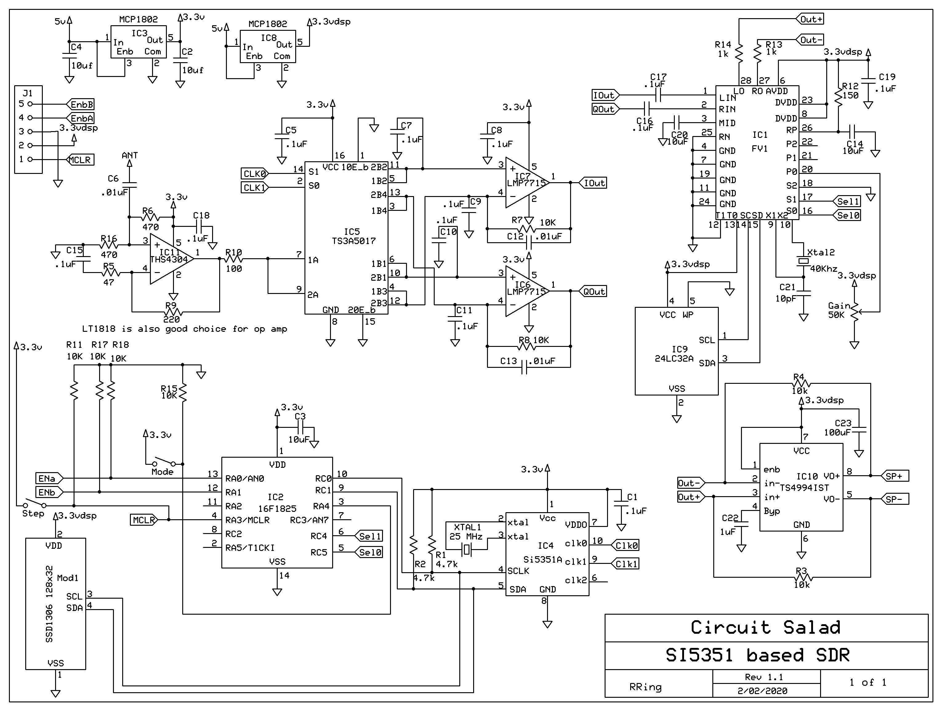
4 layers37.8 × 42.9 mmTS3A5017-Mixer, the printed circuit board in 3D

Repository of stuff to learn about and build an SDR

Size
37.8 × 42.9 mm
Copper layers
4
Thickness
1.58 mm
Parts
26
Nets
13
Pads
122
Tracks, vias
159, 32
Pours
2
Routed
Yes
KiCad
KiCad 8.0 (file 20240108)
Created
23 Mar 2024
Updated
13 Apr 2024

Overview

TS3A5017-Mixer is an open-source printed circuit board by brokebit, from the brokebit/SDR-Learning-Project repository on GitHub. It is a 4-layer board of 37.8 × 42.9 mm with 26 parts on 13 nets, routed with 159 tracks and 32 vias.

It is built around the LMP7715MF and TS3A5017RGY. Its parts include 15 capacitors, 5 connectors, 3 ICs and 2 resistors. It belongs with the audio and music boards of this library.

Main components

2

README

README.md

SDR-Learning-Project

Repository of stuff to learn about and build an SDR

Learning Projects

  • Mixer Board TS3A5017 (Direct Reciever)
  • Op Amp
  • Front End Amp
  • Frequency Synthesizer
  • Bandpass Filter

SDR Radio Research

Chips

Basics

Quadrature Signals

Phase Locked Loop (PLL):

Create stable signal reference. Use a stable low freq reference (Crystal) to stabilize a high freq unstable ref (VCO).

Voltage Controlled Oscillator (VCO)

  • Usually unstable, and require something like a PLL to stabilize

Operational Amplifiers

  • https://www.youtube.com/watch?v=7FYHt5XviKc
  • Gain is huge
  • In open loop configuration, they are just comparators; Add negative feedback to become amplifiers rather than comparators
  • If non-inverting input is higher than inverting input, output will be V+
  • If non-inverting input is lower than inverting input, output will be V-
  • Called "Operational" cause they were designed to perform mathematical "operations."
  • Can be used as a buffer in buffer configuration
  • Input impedance is high, so won’t draw current or effect anything on the input side
  • Output impedance is low, so you can drive a bit of current through it. Tens of milliamps
  • Non-Inverting Amp Configuration (Single Ended Amp)
    • Gain = Rf/R1 + 1
  • Inverting Amp configuration
    • Gain = Rf/R1
    • Input * Gain * -1
    • With DC supply, it can never go negative. So need to off set and can do that by supply 1/2 Vcc to non-inverting pin

Radio Designs

Filters

Receive

Transmit

Mixing and Switching

https://www.allaboutcircuits.com/technical-articles/how-to-multiply-RF-signals-without-a-multiplier-the-switching-mixer/

Tayloe Detector/Mixer:

RF Board Design

Research needed

  • Impedance and traces - Use either JLC PCB impedance calculator or one built into KiCad
  • Stackups and Ground planes - Use four layers or more. Put RF traces on top or bottom layers. Always a Ground plane above or bellow the RF layer for return currents
  • Stripline: Internal Trace
  • Microstrip: Outer layer trace

Parts

26
QtyValueFootprintReferences
13.1ufCapacitor_SMD:C_0201_0603MetricC1, C2, C3, C4, C5, C6, C7, C8, C9, C10, C11, C12, C13
210kResistor_SMD:R_0201_0603MetricR1, R2
21ufCapacitor_SMD:C_0201_0603MetricC14, C15
2LMP7715MFPackage_TO_SOT_SMD:SOT-23-5U2, U3
1CLK0Connector_Coaxial:SMA_Amphenol_901-143_HorizontalJ2
1CLK1Connector_Coaxial:SMA_Amphenol_901-143_HorizontalJ3
1Conn_01x02_PinConnector_PinHeader_2.54mm:PinHeader_1x02_P2.54mm_VerticalJ4
1LOGOLOGOG***
1PJ-320D-AConnector_Audio:HRO_PJ-320D-AJ5
1RF-InConnector_Coaxial:SMA_Amphenol_901-143_HorizontalJ1
1TS3A5017RGYPackage_DFN_QFN:Texas_RGY_R-PVQFN-N16_EP2.05x2.55mmU1

More from brokebit/SDR-Learning-Project

1
  • 4 layers40.9 × 18 mmLowPassFilter, the printed circuit board in 3D

    LowPassFilter

    brokebit/SDR-Learning-Project

    Repository of stuff to learn about and build an SDR

    8 parts
Similar boards

  • 2 layers139.7 × 41.9 mmKstat mainboard, the printed circuit board in 3D

    Kstat mainboard

    nfroehberg/GlazerLab_KStat

    Firmware, PCB design and Python interface for the KStat potentiostat developed in the Glazer Lab, University of Hawaii.

    121 parts
  • 4 layers19 × 76 mmMozc doublesided, the printed circuit board in 3D

    Mozc doublesided

    google/mozc-devices

    Circuit diagrams and firmware source code for Gboard DIY keyboards

    26 parts3kApache-2.0
  • 4 layers15 × 15 mmDRV8213 brushed Motor Driver, the printed circuit board in 3D

    DRV8213 brushed Motor Driver

    hackclub/OnBoard

    💡 Join 1,000 teenagers and make your first PCB with a $100 grant!

    26 parts915
  • 4 layers82.5 × 39.4 mmV4head, the printed circuit board in 3D

    V4head

    makerforgetech/modular-biped

    An open source framework for creating a bipedal modular companion robot.

    26 parts493GPL-3.0
  • 4 layers101 × 27 mmEthernet inline probe, the printed circuit board in 3D

    Ethernet inline probe

    azonenberg/starshipraider

    Open hardware test equipment

    26 parts193BSD-3-Clause
  • 4 layers12 × 12 mmFemto v1, the printed circuit board in 3D

    Femto v1

    mfolejewski/FEMTO

    FEMTO - RP2040 12x12mm PCB module

    26 parts159
  • 4 layers40 × 15 mmNlink lite, the printed circuit board in 3D

    Nlink lite

    nspired-Hackers/nternet-Link

    Wi-Fi, AI chat, and camera module for TI-Nspire calculators. Custom ESP32 PCBs + firmware. (Yes, 'nternet' is intentional, Nspire community naming.)

    26 parts58

Questions

How big is the TS3A5017-Mixer PCB?

It measures 37.8 × 42.9 mm and has 4 copper layers, 1.58 mm thick.

What parts does the TS3A5017-Mixer use?

26 parts, built around the LMP7715MF and TS3A5017RGY. The full list of its parts is on this page, with links to each part's symbol and footprint where PCBKit's library has them.

Where can I download the TS3A5017-Mixer KiCad files?

From the brokebit/SDR-Learning-Project repository on GitHub, at the commit this page was made from: the board is Mixer Board/TS3A5017-Mixer/TS3A5017-Mixer.kicad_pcb and its schematic Low Pass Filter Board/LowPassFilter/LowPassFilter.kicad_sch. PCBKit opens the board in the browser, with nothing to install.

Can I use the TS3A5017-Mixer design in my own project?

Its repository states no licence, so its author keeps all rights: ask brokebit before reusing the design.