Skip to the content
PCBKitNew board
2 layers20.3 × 20.3 mmPcb2, the printed circuit board in 3D

info + code for 5g sensor

Size
20.3 × 20.3 mm
Copper layers
2
Thickness
1.6 mm
Parts
12
Nets
8
Pads
32
Tracks, vias
68, 6
Routed
Yes
KiCad
KiCad 7 (file 20221018)
Created
23 Sep 2025
Updated
3 Oct 2025

Overview

Pcb2 is an open-source printed circuit board by braedouble, from the braedouble/5g_sensor_docs repository on GitHub. It is a 2-layer board of 20.3 × 20.3 mm with 12 parts on 8 nets, routed with 68 tracks and 6 vias.

It is built around the ICM-42688-P. Its parts include 3 capacitors, 2 connectors and 1 IC.

Main components

1

README

README.md

Hardware

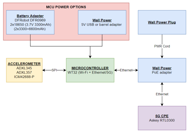
  • My sensor (Diagram)
    • My sensor parts
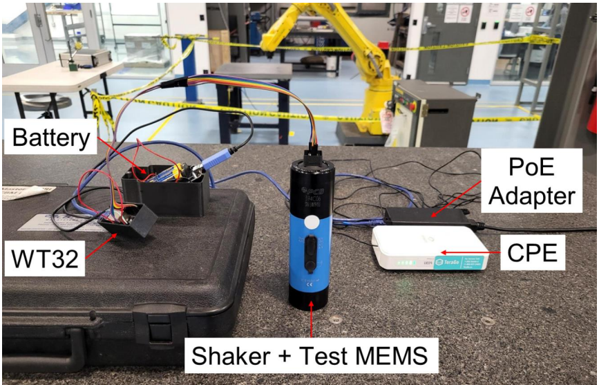
  • My sensor (On shaker)
    • Sensor on shaker

5G Connection

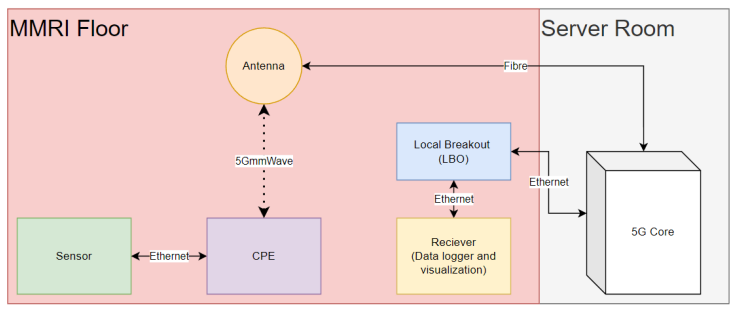
  • Sensor connects to 5G via ethernet CPE access point
  • Connects to a device connected directly to the 5G core server
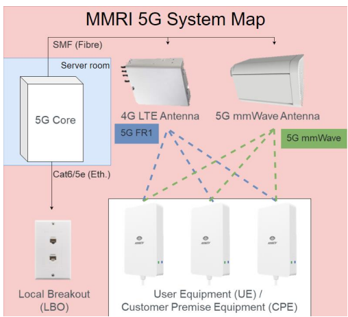
    • This port is connected to an ethernet port in the lab, the local breakout port (LBO) 5G map 5G map

MCU

Accelerometer

All read via SPI (analog sensor add ADC)

Software

Libraries

All info based on register functions from accelerometer datasheets

  • ICM42688-P
    • mainly based on https://github.com/finani/ICM42688
    • some changes to try to make SPI reads faster and match some functions to my other accelerometer libraries
    • did some work to get FIFO working to try for 32 kHz output
    • tested and working with 5G and ethernet at 16kHz ODR with interrupt method

Platformio/ESP32

Receiver

  • Require python and matplotlib library (rest of libraries should be built in)

Setup

  • Follow platformio setup
  • Setup WT32 for programming per the guide
  • Code should be okay to upload to sensor
    • sensor
      • set IP address and port number of receiver
    • receiver
      • match port number to sensor
  • Change to run mode and connect to a python reader

FOR SENSOR

  • Needs valid network info (reader IP address and port)
  • Sensor settings for Hz and range are set via code still I think for ICM, controls need to be finished
  • 16kHz max ODR for SPI without FIFO right now

FOR RECEIVER

  • Needs port set for same as reader
  • Needs sensor on and running first

Lathe Tool Holder Previous Works

  • Bleicher 2018, 2020, 2023 (Milling)
    • Schorghofer 2019
    • Ramsauer 2021 (not much sensor info added here)

Main Changes

  • Mounting (tool holder)
    • machine considerations (chips, coolant, heat)
    • cpe placement / battery life
  • Read selected sensors
  • Rec./Controller updates + database implementation
  • Sensor connection / reconnection handling

Parts

12
QtyValueFootprintReferences
4MountingHoleMountingHole:MountingHole_3mmH1, H2, H3, H4
2Conn_01x04_PinConnector_PinHeader_2.54mm:PinHeader_1x04_P2.54mm_VerticalJ1, J2
1.1uFCapacitor_SMD:C_0402_1005MetricC1
110nFCapacitor_SMD:C_0402_1005MetricC3
12.2uFCapacitor_SMD:C_0402_1005MetricC2
1ICM-42688-PICM-42688-P:PQFN50P300X250X97-14NU1
1LOGOlogo:10mm_logoG***
1LOGOlogo:logo, .75G***

Questions

How big is the Pcb2 PCB?

It measures 20.3 × 20.3 mm and has 2 copper layers, 1.6 mm thick.

What parts does the Pcb2 use?

12 parts, built around the ICM-42688-P. The full list of its parts is on this page, with links to each part's symbol and footprint where PCBKit's library has them.

Where can I download the Pcb2 KiCad files?

From the braedouble/5g_sensor_docs repository on GitHub, at the commit this page was made from: the board is ICM42688-P_PCB/pcb2/pcb2.kicad_pcb and its schematic ICM42688-P_PCB/pcb2/POP1_kicad/POP1_kicad.kicad_sch. PCBKit opens the board in the browser, with nothing to install.

Can I use the Pcb2 design in my own project?

Its repository states no licence, so its author keeps all rights: ask braedouble before reusing the design.

Similar boards

  • 4 layers39 × 39 mmOneInchEye, the printed circuit board in 3D

    OneInchEye

    will127534/OneInchEye

    A One Inch CMOS sensor (IMX283) camera board designed for Raspberry Pi

    94 parts355MIT
  • 6 layers39.5 × 39.5 mmLEVIA H7, the printed circuit board in 3D

    LEVIA H7

    piecol/LEVIA-H7

    Open hardware STM32H743 drone flight controller

    173 parts71CERN-OHL-S-2.0
  • 8 layers38.5 × 38.5 mmFlight Controller, the printed circuit board in 3D

    Flight Controller

    rishikesh2715/STM32F7_FC

    STM32F722RET6 Based Flight Controller with ICM-42688-P IMU, BMP388 Barometer, and much more!

    133 parts57MIT
  • 4 layers66.4 × 66.4 mmRera, the printed circuit board in 3D

    Rera

    fdiwth/tvc-drone

    This repository contains the documentation, hardware designs, and source code for a Thrust Vector Control (TVC) drone.

    140 parts34GPL-3.0
  • 4 layers39 × 39 mmGlobalEye, the printed circuit board in 3D

    GlobalEye

    will127534/GlobalEye

    A simple camera board using GMAX3412 1" 4K@30fps global shutter sensor

    148 parts31MIT
  • 4 layers33 × 65.5 mmOM FlexGrid Rigid PCB, the printed circuit board in 3D

    OM FlexGrid Rigid PCB

    Open-Muscle/OpenMuscle-FlexGrid

    60-sensor wearable with flexible PCB and pressure matrix

    65 parts19CERN-OHL-S-2.0
  • 4 layers36 × 36 mmOpenuav, the printed circuit board in 3D

    Openuav

    catphish/openuav

    An open source unmanned aerial vehicle

    80 parts12MIT
  • 6 layers36 × 36 mmNewSkyH7-Air, the printed circuit board in 3D

    NewSkyH7-Air

    kuku-199/NewSky

    159 parts10Apache-2.0