2 layers132.4 × 70.8 mm

 bpmine/jarduino
Ensemble de systèmes pour l'arrosage du jardin
Jard rs485 slave m0 is an open-source printed circuit board by bpmine, from the bpmine/jarduino repository on GitHub. It is a 2-layer board of 78.6 × 30 mm with 68 parts on 55 nets, routed with 500 tracks and 66 vias.
It is built around the ATSAMD21G18A-AU, MAX3485ED and BAV99, with the 1N4007G, RDS-16S-74385-SMT and SMBJ18A among its other parts. Its parts include 18 capacitors, 17 resistors, 12 diodes, 4 ICs and 4 connectors. It belongs with the interfaces and adapters boards and the SAM D and SAM boards of this library.


Le Jarduino est un ensemble de systèmes pour l'arrosage du jardin.
Il comporte les sous-ensembles suivants:
Le principal objectif du projet est de s'amuser tout en mettant à profit les compétences acquises lors d'une réponse à un cahier des charges pour un projet professionnel qui n'a finalement pas abouti.
La réalisation inclue des cartes électroniques conçues sur mesure, du logiciel, quelques petites pièces mécaniques et bien d'autres éléments....
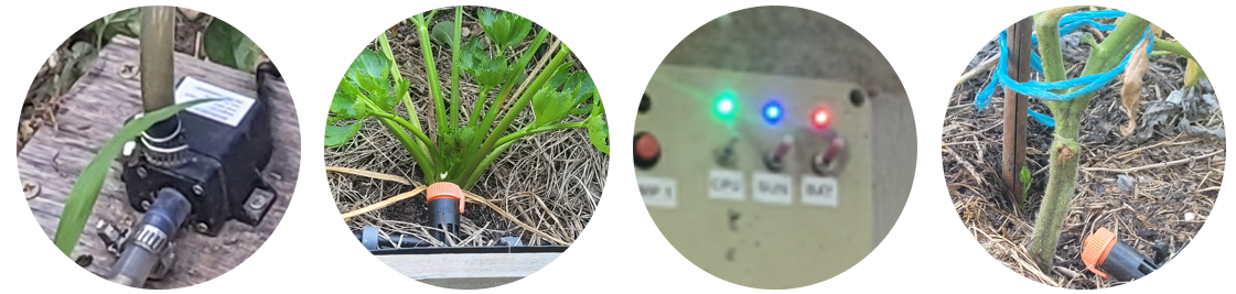
Le système de goutteurs est le "Jarduino" historique, mis en place assez rapidement (en 2019 ?) pour partir en vacances sans s'occuper de l'arrosage.
Il a fonctionné presque jusqu'au bout. Le panneau solaire s'est retourné (vent?), et sans énergie, il s'est arrêté...
Depuis 2019, chaque année, le Jarduino fonctionne toujours en se perfectionnant. Il a compté jusqu'à une cinquantaine de goutteurs en 2022.
Ce Jarduino est un peu plus sérieux, basé sur de vraies cartes électroniques et non plus sur des platines de prototypage.
Il a été prévu en deux étapes:
Il a fonctionné sans difficultés. Mais le module Wifi n'est toujours pas prêt (en 2024)...
Une cuve permet de stoker de l'eau. Un boîtier de contrôle alimenté par un panneau solaire avec une batterie pilote une pompe qui allimente les goutteurs. Le boîtier pilote jusqu'à deux pompes et peut être programmé à une heure donnée pour une durée d'arrosage souhaitée.
Voir ici la description détaillée: Système de goutteurs
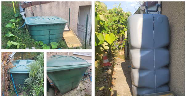
Plusieurs cuves récupèrent l'eau de pluie et permettent d'approvisioner les systèmes d'arrosage automatiques. Un système de pompes contrôlables à distance permet de gérer leur niveau.
Voir ici la description détaillée: Gestion des cuves
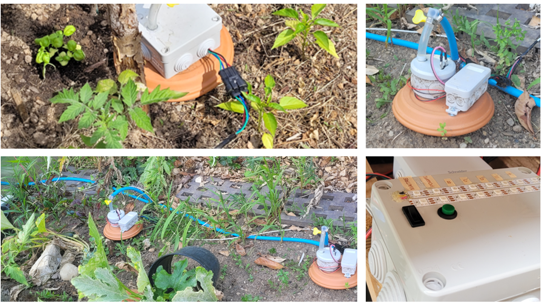
Le système permet de diffuser de l'eau aux plantes par la terre grâce à des sortes de petites jarres en argile appellées OYAs. Ce dispositif a été déployé après les goutteurs, en 2023. Il remplace petit à petit le système de goutteurs.
Voir ici la description détaillée: Gestion des OYAs
| Qty | Value | Footprint | References |
|---|---|---|---|
| 10 | 100k | Resistor_SMD:R_0805_2012Metric_Pad1.20x1.40mm_HandSolder | R3, R4, R6, R7, R8, R9, R12, R13, R15, R16 |
| 6 | 100nF | Capacitor_SMD:C_0805_2012Metric_Pad1.18x1.45mm_HandSolder | C2, C8, C9, C10, C17, C20 |
| 4 | 100nF | Capacitor_SMD:C_0603_1608Metric_Pad1.08x0.95mm_HandSolder | C4, C5, C11, C15 |
| 4 | BAV99 | Package_TO_SOT_SMD:SOT-23 | D1, D2, D6, D8 |
| 3 | 1k | Resistor_SMD:R_0805_2012Metric_Pad1.20x1.40mm_HandSolder | R1, R2, R14 |
| 2 | 10µF | Capacitor_SMD:CP_Elec_4x5.4 | C16, C19 |
| 2 | 1nF | Capacitor_SMD:C_0805_2012Metric_Pad1.18x1.45mm_HandSolder | C3, C18 |
| 2 | SD12_SOD323 | bpc:BPC_D_SOD-323_HandSoldering | D7, D10 |
| 1 | 0 | Resistor_SMD:R_0805_2012Metric_Pad1.20x1.40mm_HandSolder | R17 |
| 1 | 10k | Resistor_SMD:R_0805_2012Metric_Pad1.20x1.40mm_HandSolder | R11 |
| 1 | 10µF | Capacitor_SMD:CP_Elec_5x5.9 | C6 |
| 1 | 10µF | Capacitor_SMD:C_0805_2012Metric_Pad1.18x1.45mm_HandSolder | C7 |
| 1 | 12V | TestPoint:TestPoint_Pad_D1.0mm | TP1 |
| 1 | 1N4007G | Diode_THT:D_A-405_P7.62mm_Horizontal | D11 |
| 1 | 1µF | Capacitor_SMD:C_0805_2012Metric_Pad1.18x1.45mm_HandSolder | C13 |
| 1 | 220 | Resistor_SMD:R_0805_2012Metric_Pad1.20x1.40mm_HandSolder | R5 |
| 1 | 27k | Resistor_SMD:R_0805_2012Metric_Pad1.20x1.40mm_HandSolder | R10 |
| 1 | 33µF | Capacitor_SMD:CP_Elec_5x5.9 | C1 |
| 1 | A | TestPoint:TestPoint_Pad_D1.0mm | TP10 |
| 1 | AP1117-15 | bpc:BPC_SOT-223-3_TabPin2 | U4 |
| 1 | ATSAMD21G18A-A | Package_QFP:TQFP-48_7x7mm_P0.5mm | U2 |
| 1 | B | TestPoint:TestPoint_Pad_D1.0mm | TP9 |
| 1 | BPC_Alim5V | bpc:BPC_Alim5V | U1 |
| 1 | BPC_FMMT38C | bpc:BPC_SOT-23-3_HandSoldering | Q1 |
| 1 | BPC_PRG_FTSH-105-01-L-DV-K_1 | bpc:BPC_SAMTEC_FTSH-105-01-L-DV-K | J5 |
| 1 | Cmd | TestPoint:TestPoint_Pad_D1.0mm | TP8 |
| 1 | EV1 | TerminalBlock_Phoenix:TerminalBlock_Phoenix_MPT-0,5-2-2.54_1x02_P2.54mm_Horizontal | J3 |
| 1 | Gnd | TestPoint:TestPoint_Pad_D1.0mm | TP2 |
| 1 | High | TestPoint:TestPoint_Pad_D1.0mm | TP3 |
| 1 | LED | LED_SMD:LED_0805_2012Metric_Pad1.15x1.40mm_HandSolder | D5 |
| 1 | LED | LED_THT:LED_D3.0mm_FlatTop | D4 |
| 1 | Low | TestPoint:TestPoint_Pad_D1.0mm | TP4 |
| 1 | MAX3485 | bpc:BPC_MAX485E_SOIC127P600X175-8N | U3 |
| 1 | Niveaux/Débit | TerminalBlock_Phoenix:TerminalBlock_Phoenix_MPT-0,5-3-2.54_1x03_P2.54mm_Horizontal | J2 |
| 1 | P03P4L-04 | Package_TO_SOT_THT:TO-220-3_Vertical | Q2 |
| 1 | POWER | TerminalBlock_Phoenix:TerminalBlock_Phoenix_MKDS-1,5-4-5.08_1x04_P5.08mm_Horizontal | J1 |
| 1 | RDS-16S-74385-SMT | bpc:BPC_RDS-16S-74385-SMT | S1 |
| 1 | Rx | TestPoint:TestPoint_Pad_D1.0mm | TP5 |
| 1 | SM712_SOT23 | bpc:BPC_SOT-23-3_HandSoldering | D9 |
| 1 | SMBJ18A | Diode_SMD:D_SMB_Handsoldering | D12 |
| 1 | SR560 | Diode_THT:D_DO-15_P12.70mm_Horizontal | D3 |
| 1 | TE | TestPoint:TestPoint_Pad_D1.0mm | TP7 |
| 1 | Tx | TestPoint:TestPoint_Pad_D1.0mm | TP6 |


eauel/openzmeter
openzmeter (oZm) is an Open Source system designed for power quality analysis and smart energy metering in power networks. It has been designed to comply with international standards IEC 61000-4-30 and EN 50160.

mgmike1011/sterownik_systemu_nawadniania_PCB
Projekt płytki drukowanej sterownika systemu nawadaniania w oparciu o STM32


ANANDHU-BIJU/HUMAN-CENTRIC-HOME-ASSISTANT-ROBOT
EVA: The robot that knows you by sight. Face recognition + voice + emotions + navigation. Open-source home intelligence for everyone.

neriyashalom/PKE-Car-System
Final project - ESP32-S3 based PKE system for vehicle access and ignition

SachinRathnayaka/Smart-Aquarium-Monitor-Control-System
Fully open-source IoT aquarium monitoring and automation system — ESP32 firmware, Firebase RTDB, Web Dashboard, Android & Windows apps, KiCad PCB

It measures 78.6 × 30 mm and has 2 copper layers, 1.6 mm thick.
68 parts, built around the ATSAMD21G18A-AU, MAX3485ED, BAV99 and 1N4007G. The full list of its parts is on this page, with links to each part's symbol and footprint where PCBKit's library has them.
From the bpmine/jarduino repository on GitHub, at the commit this page was made from: the board is oyas/slaves_rs485/carte_m0/cao/jard_rs485_slave_m0.kicad_pcb and its schematic cuves/carte_c3/cao/jard_c3.kicad_sch. PCBKit opens the board in the browser, with nothing to install.
Its repository states no licence, so its author keeps all rights: ask bpmine before reusing the design.