
2 layers134 × 88 mm
Tulipcc
shorepine/tulipcc
The Tulip Creative Computer and AMYboard - portable Python synthesizers
103 parts978

 bmatcuk/edge-lit-display
A laser-etched acrylic edge-lit display including schematics, pcb, and laser cut enclosure.
Edge lit display is an open-source printed circuit board by bmatcuk, from the bmatcuk/edge-lit-display repository on GitHub. It is a 2-layer board of 204 × 20 mm with 48 parts on 58 nets, routed with 392 tracks and 71 vias.
It is built around the 1N4148WS. Its parts include 10 capacitors, 9 diodes, 8 resistors, 2 ICs and 2 connectors. It belongs with the lEDs and displays boards and the AVR (ATmega, ATtiny) boards of this library.
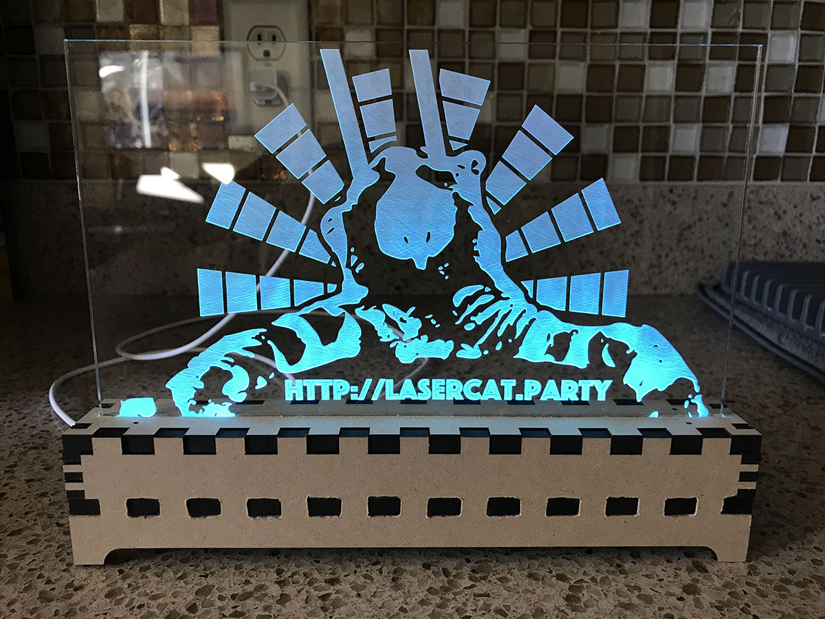
This repository contains everything you need to build an edge-lit display using RGB LEDs and laser etched acrylic with a laser cut enclosure.
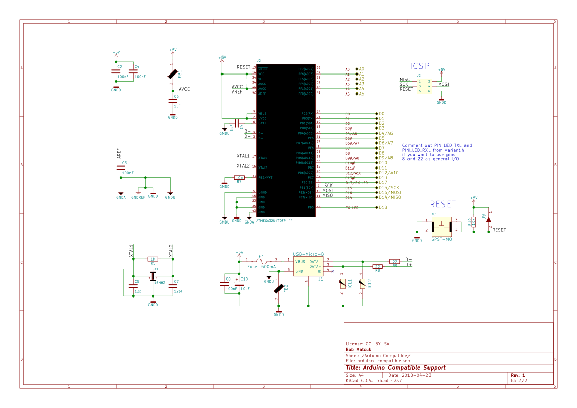
The display is controlled by an ATmega32U4, the same microcontroller used in several Arduino boards. It is flashed as an Arduino Leonardo over the ICSP header to make it easier to work with, using an actual Arduino as the programmer. The design surrounding the ATmega32U4 support circuitry, including the USB connections, is based on the Arduino Leonardo schematics.
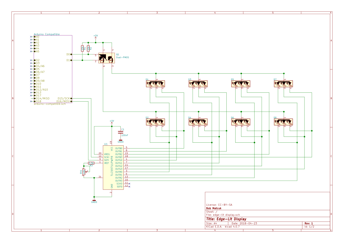
The microcontroller communicates with a TLC5971 over SPI to drive the eight RGB LEDs. The TLC5971 is a 12-channel, constant-current sink, 16-bit PWM LED driver (ie, capable of driving four RGB LEDs at a time). Therefore, the eight RGB LEDs are divided into two groups and time-multiplexed by the microcontroller using two high-side PMOS transistors. This allows us to address each channel of each LED individually.
This circuit is then fitted into a laser cut enclosure with the LEDs directed into the edge of a laser etched acrylic display. The code on the microcontroller cycles the colors of the LEDs by rotating through all possible values for "hue" in the HCY (hue-chroma-luma) colorspace, and converting to 16- bit RGB for transmission to the TLC5971.
The whole thing is powered using a standard USB 2.0 cable and includes a potentiometer to control the brightness of the LEDs by varying the current- setting resistance of the TLC5971.
Schematics were designed in KiCad v4. This repository has a dependency on my
own part library and assumes that my part library is located in the same
path as this repository (ie, the edge-lit display and bmatcuk-kicad-library
directories live in the same directory).
This first schematic is the ATmega32U4, USB, and support circuitry:
The next schematic connects the microcontroller to the LEDs, driver, and high- side PMOS to time-multiplex the LED groups:
The PCB was designed in KiCad v4. This repository has a dependency on my
own part library and assumes that my part library is located in the same
path as this repository (ie, the edge-lit display and bmatcuk-kicad-library
directories live in the same directory).
The circuit is laid out as a two-layer design. The front layer contains all of the components and a ground plane with the back layer as a signal layer. This is probably the weakest part of the whole project as this is the first time I've laid out a circuit with so many surface mount components in a constrained space.

The enclosure was designed in FreeCAD 0.17 assuming it would be made out of MDF wood with a thickness of 0.251in and laser kerf of 0.011in. The screen was designed for acrylic with a thickness of 3mm and a laser kerf of 0.2mm. These values can be easily modified in FreeCAD by editing the spreadsheet called "Datum"; the rest of the design will update automatically.
Once the design was complete, 2D projections were made of each piece and these projections were exported as "flattened svgs". The resulting svg was edited in Inkscape to conform to the format that the manufacturer wanted (ie, to make the cuts blue, for example).
The svg below might be really difficult to see on your screen because the stroke width is only 0.01mm. This was a requirement from where I had the parts laser cut.

The outline of the screen was designed in FreeCAD with the enclosure. Once the 2D projection was exported as an svg (as mentioned above), it was imported into Inkscape to create the design. Originally, I was going to do some sort of cityscape, but then I thought it would be more fun to tie this back to a previous passion project of mine: lasercat.party (github: lasercatparty)!
I edited the photo of the cat in Photoshop to remove the background, convert to greyscale, and then darken some of the light areas with the burn tool, and lighten some of the dark areas with the dodge tool. The image was then imported into Inkscape and I used the "Trace Bitmap" function to vectorize it. This was an iterative process: adjusting light and dark areas in Photoshop, re- importing in Inkscape to vectorize, etc, until I was happy with the result. The rest of the design was done entirely in Inkscape. Then everything was grouped together and flipped horizontally so that it could be etched on the back of the acrylic.
The Photoshop file is also included in this repository (cat.psd).
Like above, it may be difficult to make out the edge cuts on your screen because the stroke width is 0.01mm.

The first step was getting the PCB, enclosure, and screen manufactured. I sent
the gerbers to ALLPCB.com for PCB manufacturing. I'm very impressed with them
and would definitely recommend. I had the boards in my hands in less than a week
and their prices are very reasonable! The enclosure and screen svgs were sent to
Ponoko for laser cutting and etching. Therefore, the MDF and acrylic
thicknesses and kerfs match their specs, and the files are formatted to their
liking (blue for cuts, black for area engraving, red for line engraving; stroke
width of 0.01mm). All electrical components were ordered from DigiKey. This
repository includes a Bill Of Material file called edge-lit display.csv which
includes all of the DigiKey part numbers. You can upload the file to their
website to add all of the parts to your cart.
With PCB and components in hand, the next step is soldering the PCB. We want to load the Arduino bootloader onto our ATmega32U4, so the first thing we'll solder is the microcontroller and support circuitry. Installing the Arduino bootloader is done via the ICSP header which uses the SPI pins on the microcontroller; these pins are also used to control the TLC5971, so we're going to leave that and most of the circuitry around it off our board for now.
Technically, I think it would be ok to solder everything before installing the bootloader because it's unlikely that any of the data will make sense to the TLC5971 and the microcontroller will tri-state all of the IO pins while flashing so all of the LEDs will be off anyway, but why risk it? Besides, pausing to flash the microcontroller mid-solder gives us an opportunity to make sure everything is working up to that point; troubleshooting will be easier with fewer components on the board.
That said, I soldered all of the passives (resistors, capacitors, and the ferrite beads), the varistors, fuse, ICSP header, diode, and ATmega32U4. I technically didn't need to solder all of the passive components, since some of them are support circuitry for the TLC5971, but it was easier to solder them all together. I then tested for any bridged pins with a multimeter, and, when I was satisfied everything looked good, I moved on to installing the bootloader.
Some tips for soldering: I did most of the soldering with a soldering iron (my trusty Hakko FX-888D) with a beveled tip (the T18-CF15). It's possible to solder everything this way with the liberal application of flux (I have a Kester 186 Flux Pen) - search for "drag soldering" tutorials. I found it was easier to solder first using this method, and then touch things up a bit with a hot air rework station (I'm using an Aoyue Int866). For example, I soldered the ATmega32U4 a little off-center; very hard to fix with an iron, but short work for the hot air station.
To install the bootloader, I flashed an Arduino Uno with the ArduinoISP. To
do this in the Arduino IDE, select the Uno as the device and open the
ArduinoISP example sketch. Make sure all of the #defines are right at the
top of the file and then upload the sketch to the Uno. Next, disconnect the
Uno from your computer and make the following connections:
Other Arduinos can be used in place of the Arduino Uno using a similar
process. You just need to figure out what pins are used for SPI (MOSI, MISO,
and SCK) and the reset pin. You can actually change the pins in the #defines
at the top of the ArduinoISP sketch.
Anyway, once the wired connections are made, reconnect the Arduino Uno to your computer. Select the Arduino Leonardo from the device menu, set the port to where the Uno is connected, change "programmer" to "Arduino as ISP", and select "Burn Bootloader". This process will take a couple minutes, but it will test to make sure installation was successful, so if you don't see any errors, you know your soldering, at least up to this point, is good.
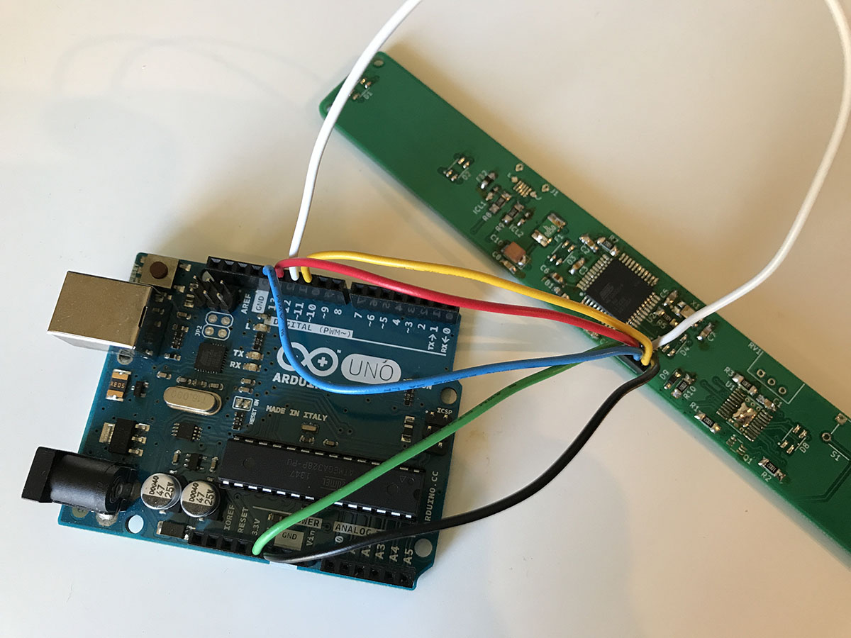
After the bootloader is installed, disconnect the Arduino Uno and solder the rest of the components. Now the sketch can be flashed via USB! Connect the PCB to your computer via USB. If all your soldering went well, you should be able to flash the code to it by selecting the Arduino Leonardo device from the Arduino IDE and uploading. You should hopefully see the LEDs cycle through all of the colors of the rainbow!
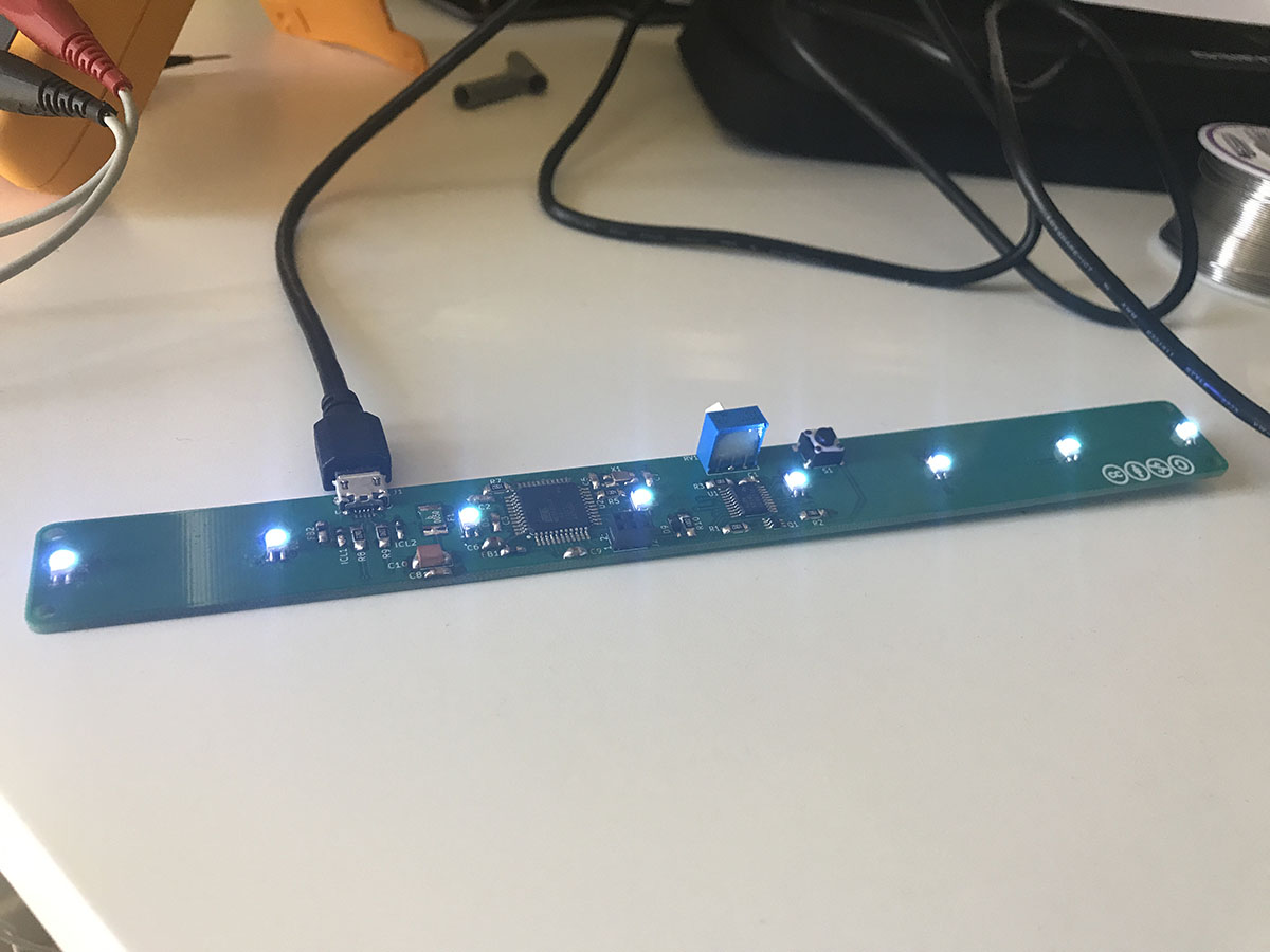
Putting the case together is fairly straightforward, but you may find that the slots are fairly tight. The company I ordered my lasercut parts from (Ponoko) didn't have very accurate measurements for wood thickness or kerf. I found the wood they sent me was around 1.5mm thicker then I was expecting. I had to use a wood file to make the pieces fit together, and, even then, they were so snug I didn't bother using any glue.
Basically, you want to put the bottom and sides together, gluing if necessary. I put the lasercut side (with the burn marks) on the inside to hide it. Then fit the PCB in. I had planned on using some M2 nylon stand-offs to mount the PCB (hence the little holes in the top and bottom pieces), but the holes ended up being too small to thread the stand-offs through. So, instead, I just hammered some nails through the bottom to keep the PCB from sliding around.
Next, slide the acrylic display through the top piece and put the top of the enclosure on. The slots on the side pieces should keep the acrylic from falling over, and should line it up to be right on top of the LEDs. If you are sucessfully using stand-offs, you can have some stand-offs go to the top of the enclosure, too.
I adjusted some of the calculations in the FreeCAD model after I received my lasercut enclosure to hopefully make it less snug. I also regenerated the enclosure.svg file, but I haven't tried getting another enclosure made up.
Software in this repository is licensed under the MIT license. Hardware schematics are released under a Creative Commons Attribution and Share Alike license (CC-BY-SA 4.0). PCB layout designs, enclosure designs, and acrylic display designs are licensed under a Creative Commons Attribution, Non- Commercial, Share Alike license (CC-BY-NC-SA 4.0).
| Qty | Value | Footprint | References |
|---|---|---|---|
| 8 | LED_ARGB | part-library:PLCC4 | D1, D2, D3, D4, D5, D6, D7, D8 |
| 5 | 100nF | part-library:0805 | C1, C2, C3, C4, C8 |
| 4 | 10k | part-library:1206 | R1, R2, R7, R10 |
| 2 | 12pF | part-library:0805 | C5, C7 |
| 2 | 1uF | part-library:0805 | C6, C9 |
| 2 | 22 | part-library:1206 | R8, R9 |
| 2 | Ferrite_Bead_30Ohm | part-library:0805 | FB1, FB2 |
| 2 | Varistor | part-library:0603 | ICL1, ICL2 |
| 1 | 10k | part-library:Bourns_3310C | RV1 |
| 1 | 10uF | part-library:1210 | C10 |
| 1 | 16MHZ | part-library:4SMD | X1 |
| 1 | 1M | part-library:1206 | R5 |
| 1 | 1N4148WS | part-library:SOD-323FL | D9 |
| 1 | 3.3k | part-library:1206 | R3 |
| 1 | ATMEGA32U4TQFP-44 | part-library:TQFP44 | U2 |
| 1 | BY | part-library:CC-BY | G*** |
| 1 | CC | part-library:CC-CC | G*** |
| 1 | CONN_03X2FEMALE | part-library:2X3 | J2 |
| 1 | Dual-PMOS | part-library:SOT-363 | Q1 |
| 1 | Fuse-500mA | part-library:1812_Concave | F1 |
| 1 | NC | part-library:CC-NC | G*** |
| 1 | SA | part-library:CC-SA | G*** |
| 1 | SPST-NO | part-library:SPST_6mm | S1 |
| 1 | TLC59711PWPR | part-library:HTSSOP-20 | U1 |
| 1 | USB-Micro-B | part-library:USB_Micro_B_Female | J1 |
The 44 most common of 48 parts.
shorepine/tulipcc
The Tulip Creative Computer and AMYboard - portable Python synthesizers

antmicro/jetson-nano-baseboard
Antmicro's open hardware baseboard for the NVIDIA Jetson Nano, TX2 NX and Xavier NX

Twisted-Fields/rp2040-motor-controller
A dual channel brushless motor controller based on the RP2040 microcontroller, designed in Kicad.

TeXitoi/keyseebee
KeySeeBee is a split ergo keyboard. It is only 2 PCB (so the name) with (almost) only SMD components on it. It's only a keyboard, no LED, no display, nothing more than keys and USB.


JanM321/esphome-lg-controller
Wired controller for LG HVAC units using ESPHome and ESP32

plinkysynth/plinky_public
a public release of the plinky sw and hw

TobleMiner/DC-UPS
A small DC UPS, designed to keep small appliances like consumer network equipment running during power outages
It measures 204 × 20 mm and has 2 copper layers, 1.6 mm thick.
48 parts, built around the 1N4148WS. The full list of its parts is on this page, with links to each part's symbol and footprint where PCBKit's library has them.
From the bmatcuk/edge-lit-display repository on GitHub, at the commit this page was made from: the board is edge-lit display.kicad_pcb. PCBKit opens the board in the browser, with nothing to install.
Its repository states no licence, so its author keeps all rights: ask bmatcuk before reusing the design.