
2 layers100 × 50 mm
Pixelix
BlueAndi/Pixelix
Full RGB LED matrix, based on an ESP32 and WS2812B LEDs or emulated LEDs on TFT.
33 parts447MIT

 BlueAndi/Pixelix447
Full RGB LED matrix, based on an ESP32 and WS2812B LEDs or emulated LEDs on TFT.
Pixelix is an open-source printed circuit board by BlueAndi, from the BlueAndi/Pixelix repository on GitHub, published under the MIT licence. It is a 2-layer board of 100 × 50 mm with 31 parts on 61 nets, routed with 222 tracks and 267 vias.
It is built around the CDSOD323-T05C. Its parts include 8 resistors, 8 connectors, 4 capacitors, 2 transistors and 1 IC. It belongs with the lEDs and displays boards and the ESP32 boards of this library.

Full RGB LED matrix, based on an ESP32 and WS2812B LEDs.


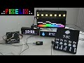
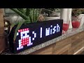
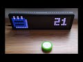
Click on the preview to see the video.


My initial goal was to have a remote display that would show multiple kind of information and run reliably 24/7. Can be connected to the local network via WiFi and controlled via REST API or Websocket. PIXELIX was born!
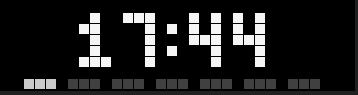
PIXELIX firmware runs on ESP32 boards and controls RGB LED matrices or TFT displays. It can display the time, date, weather, text, animations, and more. It requires no cloud connection or smart home system, but its REST and MQTT APIs integrate with Home Assistant and other smart home systems.
Not every feature is available on every development board. For example, MQTT generally requires a board with at least 8 MB of flash, except for the Ulanzi TC001. See the config<variant>.ini files in the config folder for details.
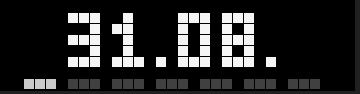
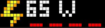
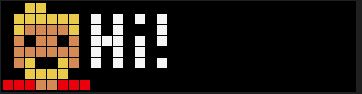
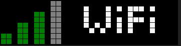
| Some impressions | |
|---|---|
 |  |
 |  |
 | ... |
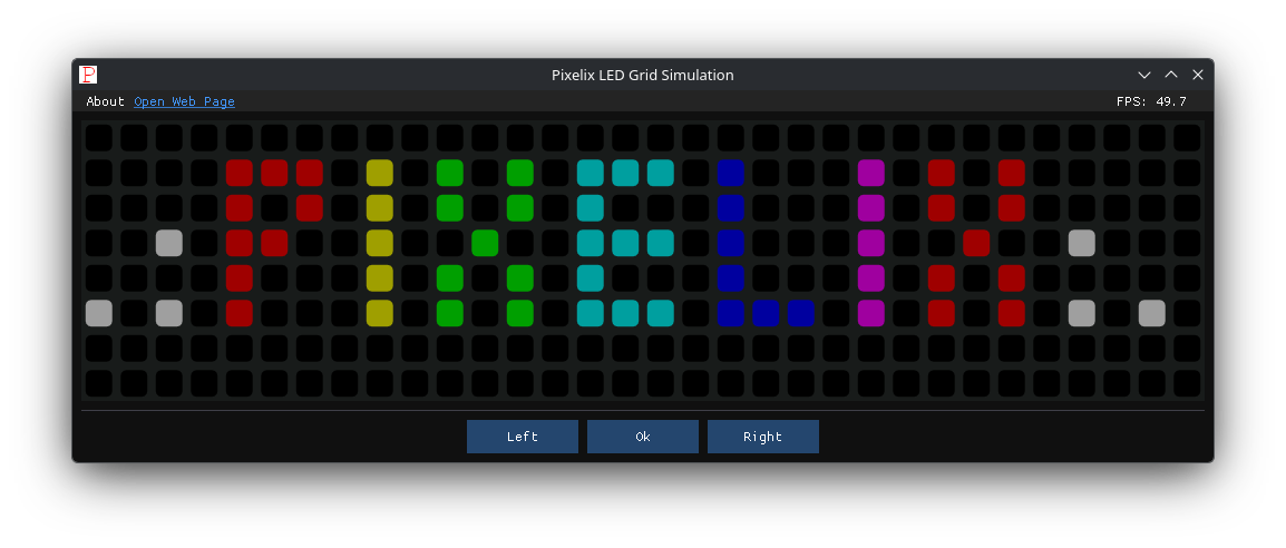
The native environment runs PIXELIX as an application on Windows and Linux without requiring hardware. It displays a simulated LED grid in a window and serves its web interface on local port 8080. Melodies that would play through a board's buzzer use the host's audio device. You can mute them with the Mute entry in the simulator window's menu bar.
The original setup for development and the first release was:
The following diagram shows the minimum wiring setup, for example, for the ESP32 DevKit V1. Wiring may differ depending on your development board.
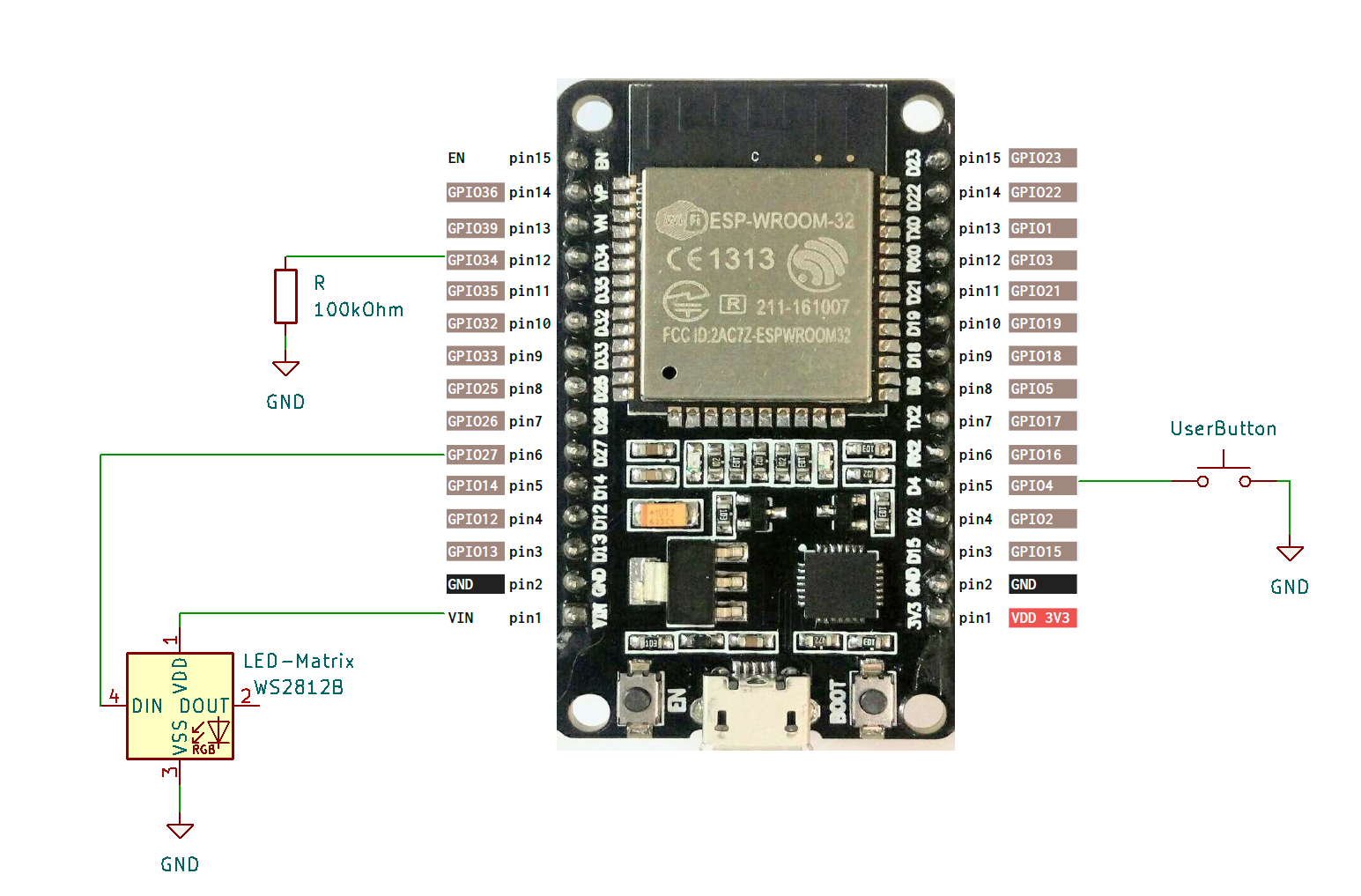
:warning: If you power the development board and LED matrix via USB, be careful: excessive LED current can damage the ESP32 board. Avoid increasing the display brightness or filling it completely with white pixels. Use an external power supply rated for at least 5 V / 4 A.
:information_source: To protect your hardware and your eyes, PIXELIX starts at a low brightness. The maximum current is also limited by software.
In the meantime several other boards are supported as well. You can find them in the list of boards. If your board is not listed in the main branch, please have a look in the Development branch too.
With the Ulanzi TC001 smart pixel clock you even don't need to assemble the electronic and mechanic together.
If you assemble your own Pixelix hardware, its recommended to use a development board with the following properties:
Additional supported variants, which were original not in focus:
Although PIXELIX was designed to show information, that is pushed or pulled via REST API, the following sensors can be directly connected and evaluated:
PIXELIX can be installed in two different ways. Decide first which one applies to you, because it determines whether you need a build toolchain at all.
| Your situation | Way to go |
|---|---|
| You use one of the supported development boards with its standard display and the panel wiring matches. | Install a prebuilt release. No toolchain required, nothing needs to be compiled. Use the web USB installer or flash the binaries manually. |
| Your board/display combination is not released, your LED matrix size or panel topology is different, you want another set of plugins, you want to rotate the display by 180° or you want to develop a plugin or fix a bug. | Build and install the software yourself. |
Every release provides ready-to-flash binaries for all supported board and display combinations. They are named after their build environment, e.g. esp32doit-devkit-v1-LED-32x8, which encodes the development board as well as the display type and its resolution.
:warning: A prebuilt binary has the LED matrix width/height, the panel topology and the list of plugins compiled in. None of them can be changed later in the web interface. If one of them does not match your hardware, you have to build the software yourself.
This is the easiest way and the recommended one for everybody who does not want to touch the source code. The installer runs completely in the browser, writes a full flash image (bootloader, partition table, factory image, firmware and filesystem) and can hand over the WiFi credentials over USB afterwards.
If the board does not enter the download mode automatically, follow the BOOT/RESET sequence shown on the page. This is typically necessary for the ESP32 DevKit V1.
Use this way if no Chromium based browser is available or if you prefer the classic Espressif tools.
:information_source: The order matters. Configure the display before the first build, because the display configuration is compiled into the firmware.
./config/display.ini:
./config/config*.ini.Independent of the way you installed PIXELIX, verify that the LED panel topology is correct and that you see the "Hello World" on the display. If the text is mirrored, scrambled or spread over the wrong rows, the panel topology does not match and the software has to be built with the right CONFIG_LED_TOPO setting.
Once PIXELIX runs and its web interface is accessible, the firmware and the filesystem can be updated over WiFi with the PIXELIX Updater: https://github.com/BlueAndi/PixelixUpdater. You can access the Updater through the submenu "Update" of PIXELIX's web interface. Reinstalling via USB is not necessary for an update.
When the device starts for the very first time, the WiFi station SSID and passphrase settings are empty. They can be configured in two possible ways:
As long as no WiFi station SSID and passphrase are configured, PIXELIX spawns a WiFi access point automatically on every startup. Just wait until it shows the SSID of the access point, search for it with your mobile device and connect.
Once the WiFi station SSID and passphrase are configured, PIXELIX connects to your WiFi network instead. To get back into the access point mode on purpose - e.g. after you replaced your router - restart the device and keep the button pressed until the access point SSID is shown.
Depending on your device, you may see a notification prompting you to open the captive portal. Otherwise, enter http://192.169.4.1 in your browser's address bar.
Use the following default credentials to get access to the PIXELIX web interface:
Connect PIXELIX to your PC via USB and start a serial terminal. Use the following commands to set the WiFi SSID and passphrase of your home WiFi network:
write wifi passphrase <your-passphrase>write wifi ssid <your-ssid>restartget ipget hostnameget status
Use help to get a list of all supported commands.
After configuration, restart PIXELIX. It will then be available on your Wi-Fi network.
To change what is displayed, open the web interface and use the same credentials as for the captive portal in Variant 1. On the Display page, configure it to suit your needs.
Pixelix can be controlled with buttons. Most of the development boards are supported with just one user button.
If the display's location is hard to reach, the remote user button feature can be used. It is controllable via REST API and perfect for remote buttons like the Shelly Button 1.
Adapt in ./config/display.ini the CONFIG_LED_MATRIX_WIDTH and CONFIG_LED_MATRIX_HEIGHT according your LED matrix and change CONFIG_LED_TOPO according to your physical panel topology. Take a look how your pixels are wired on the pcb and use the following page to choose the right one: https://github.com/Makuna/NeoPixelBus/wiki/Layout-objects
Text properties can be changed using different keywords added to the string to be displayed. In order to be able to use these keywords, they must be inside curly braces, otherwise they will only be treated as text.
The following keywords are available:
| Keyword | Description |
|---|---|
{#RRGGBB} | Set solid text color (RRGGBB in hex) |
{lgv #RRGGBB,#RRGGBB,OFFSET,LENGTH} | Set linear vertical gradient text color (RRGGBB in hex, OFFSET/LENGTH in pixels) |
{lgh #RRGGBB,#RRGGBB,OFFSET,LENGTH} | Set linear horizontal gradient text color (RRGGBB in hex, OFFSET/LENGTH in pixels) |
{stc} | Activate solid text color |
{lgtc} | Activate linear gradient text color |
{hl} | Horizontal alignment left |
{hc} | Horizontal alignment right |
{hr} | Horizontal alignment center |
{vt} | Vertical alignment top |
{vc} | Vertical alignment center |
{vb} | Vertical alignment bottom |
{0xCC} | Special character code (CC in hex) |
Notes:
Examples:
| Sourcecode | URL | Result |
|---|---|---|
{hl}{#ff0000}Hi! | %7Bcl%7Dff0000Hi! | Hi! |
{hc}{#ff0000}Hi! | %7Bhc%7Dff0000Hi! | Hi! |
{hr}{#ff0000}Hi! | %7Bhr%7Dff0000Hi! | Hi! |
This is a low level error code. Please have a look into the following table.
| Error code | Description |
|---|---|
| E1 | Something happened, which can not be further explained, but was fatal. |
| E2 | There is a problem with the two-wire (i2c) interface. |
| E3 | There is no user button available. |
| E4 | Bad filesystem, did you explicit program the filesystem too? If not, please upload it. |
| E5 | The display manager didn't start up. |
| E6 | The system message handler didn't start up. |
| E7 | One of the services failed to start. |
Press a button and Pixelix will jump to the Pixelix Updater.
Use animated GIF images to get animated icons. The sprite sheet support (< v8.0.0) was replaced with the GIF images.
If you like to create animated GIFs by yourself, the Piskel editor is recommended. Piskel is a free online editor for animated sprites & pixel art.
The LDR pin is configured as input (ADC) and it seems that the pin is floating, because there is the ext. pull-down missing.
Find details in the icon page.
There are three font types defined:
Note, the default font type is "normal".
The font type can be selected per plugin instance in the display web page.
Not all plugin may support this in case they get conflicts with their layout. If a plugin don't support it, it will use the default font type.
The date/time format used by plugins, e.g. the DateTimePlugin or the SunrisePlugin, can be configured in their configuration JSON file. Use the file editor in the web interface to modify it according to your needs. The file can be found in the /configuration folder and the filename is <PLUGIN-UID>.json. The format specifiers following strftime().
Examples:
%I:%M %p: 02:30 PM%H:%M: 14:30%m/%d: 11/12%d.%m.: 11.12.%d - %b: 11 - NovYou can colorize it by using the text properties.
The available plugins depend on your development board. Boards with only 4 MB of flash cannot fit every plugin, and single-core boards such as the ESP32-S2 may not have enough processing power for some plugins.
Several .ini files in the ./config folder define plugin sets:
Edit the file used by your board, commenting plugins in or out as needed.
Change option CONFIG_DISPLAY_ROTATE180 in config/display.ini to 1 as shown below and rebuild.
Example:
[display:common]
build_flags =
-D CONFIG_DISPLAY_ROTATE180=1| Library | Description | License |
|---|---|---|
| Arduino | ESP32 Arduino framework v2.x.x | Apache-2.0 |
| PlatformIO | PlatformIO is a cross-platform, cross-architecture, multiple framework, professional tool for embedded systems engineers and for software developers who write applications for embedded products. | Apache-2.0 |
| NeoPixelBus | Controlling the LED matrix with hardware support (I2S) | LGPL-3.0 |
| ESPAsyncWebServer | Webserver | LGPL-3.0 |
| AsyncTCP | This is a fully asynchronous TCP library, aimed at enabling trouble-free, multi-connection network environment for Espressif's ESP32 MCUs. | LGPL-3.0 |
| ArduinoJson | JSON handling | MIT |
| StreamUtils | Stream utilities | MIT |
| Bootstrap | CSS Framework | MIT |
| POPPER JS | POPPER JS | MIT |
| Adafruit Unified Sensor Driver | A unified sensor abstraction layer. | Apache License 2.0 |
| Adafruit DHT sensor library | An Arduino library for the DHT series of low-cost temperature/humidity sensors. | MIT |
| arduino-sht | An Arduino library for reading the SHT3x family of temperature and humidity sensors. | BSD-3-Clause |
| TFT_eSPI | Arduino and PlatformIO IDE compatible TFT library optimised for the Raspberry Pi Pico (RP2040), STM32, ESP8266 and ESP32 that supports different driver chips | Mixed licenses: MIT, BSD, FreeBSD |
| arduinoFFT | Fast Fourier Transform for Arduino. | GPL 3.0 |
| mufonts | A collection of fonts compatible with Adafruit GFX library. These fonts were developed when creating various samples for mupplet display code. | MIT |
| JSZip | A library for creating, reading and editing .zip files with JavaScript, with a lovely and simple API. | MIT |
| FileSaver.js | FileSaver.js is the solution to saving files on the client-side. | MIT |
| Arduino client for MQTT | This library provides a client for doing simple publish/subscribe messaging with a server that supports MQTT. | MIT |
| ESP32-PSRamFS | ESP32-PsRamFS is a pseudo RamDisk library for Arduino-ESP32, with vfs compliance. | MIT |
| Dear ImGui | ImGui is a bloat-free graphical user interface library for C++. Is is used by the native Platfrom only to create a simulated LED grid window. | MIT |
| PNGdec | PNG image decoding. Only built for boards with PSRAM. | Apache-2.0 |
| libwebp | WebP image decoding (static and animated), vendored decoder-only. Only built for boards with PSRAM. | BSD-3-Clause, plus an additional patent grant |
If you have ideas or found a bug, create an issue. If you want to fix it yourself, clone the repository and open a pull request. For questions to the community or showing the own Pixelix, the Discord server can be used.
The whole source code is published under the MIT license. Consider the different licenses of the used third party libraries too!
Unless you explicitly state otherwise, any contribution intentionally submitted for inclusion in the work by you, shall be licensed as above, without any additional terms or conditions.
| Qty | Value | Footprint | References |
|---|---|---|---|
| 5 | Conn_01x02 | footprints:66200211022 | J1, J2, J4, J6, J8 |
| 4 | 100 | Resistor_SMD:R_1206_3216Metric_Pad1.30x1.75mm_HandSolder | R5, R6, R7, R8 |
| 4 | MountingHole_Pad | MountingHole:MountingHole_2.2mm_M2_Pad_Via | H1, H2, H3, H4 |
| 3 | 100n | Capacitor_SMD:C_1206_3216Metric_Pad1.33x1.80mm_HandSolder | C1, C3, C4 |
| 2 | Conn_01x03 | footprints:66200311022 | J3, J7 |
| 1 | 1.2k | Resistor_SMD:R_1206_3216Metric_Pad1.30x1.75mm_HandSolder | R3 |
| 1 | 1000u / 16V | footprints:CP_Radial_D8.0mm_P3.50mm_horizontal | C2 |
| 1 | 100k | Resistor_SMD:R_1206_3216Metric_Pad1.30x1.75mm_HandSolder | R4 |
| 1 | 10k | Resistor_SMD:R_1206_3216Metric_Pad1.30x1.75mm_HandSolder | R1 |
| 1 | 1k | Resistor_SMD:R_1206_3216Metric_Pad1.30x1.75mm_HandSolder | R2 |
| 1 | 4A | footprints:FUSE_0154004.DR | F1 |
| 1 | Adafruit_Feather_V2_ESP32 | footprints:Adafruit_Feather_V2_ESP32 | A1 |
| 1 | CDSOD323-T05C | footprints:CDSOD323-T05C | D1 |
| 1 | Conn_02x05_Odd_Even | footprints:61201021621 | J5 |
| 1 | ESP32-DEVKITC-32D | footprints:MODULE_ESP32-DEVKITC-32D | U1 |
| 1 | LOGO | footprints:Pixelix_Logo_footprint | G*** |
| 1 | NMOS_GSD_BSS138 | Package_TO_SOT_SMD:SOT-23_Handsoldering | Q1 |
| 1 | PMOS_GDS_STD26P3LLH6 | Package_TO_SOT_SMD:TO-252-3_TabPin2 | Q2 |
It measures 100 × 50 mm and has 2 copper layers, 1.6 mm thick.
31 parts, built around the CDSOD323-T05C. The full list of its parts is on this page, with links to each part's symbol and footprint where PCBKit's library has them.
From the BlueAndi/Pixelix repository on GitHub, at the commit this page was made from: the board is doc/boards/pixelix/v2.0/Pixelix.kicad_pcb and its schematic doc/boards/pixelix/v2.0/ESP32.kicad_sch. PCBKit opens the board in the browser, with nothing to install.
Its repository publishes it under the MIT licence: you may reuse it on that licence's terms (keep the author's notice, and for a copyleft licence share your changes alike).
BlueAndi/Pixelix
Full RGB LED matrix, based on an ESP32 and WS2812B LEDs or emulated LEDs on TFT.


5haman/especcy
Thumb-sized ESP32 ZX Spectrum handheld, 24 × 38 × 12 mm: FreeCAD enclosure, KiCad carrier study and cycle-timed 48K emulator firmware.


joeycastillo/Sensor-Watch
A board replacement for the classic Casio F-91W wristwatch

hoglet67/RGBtoHDMI
Bare-metal Raspberry Pi project that provides pixel-perfect sampling of Retro Computer RGB/YUV video and conversion to HDMI

hackclub/OnBoard
💡 Join 1,000 teenagers and make your first PCB with a $100 grant!

openwch/ch32v003
CH32V003 is an ultra-cheap RISC-V MCU with 2KB SRAM, 16KB flash, and up to 18 GPIOs that sells for under $0.10