2 layers111.5 × 55.8 mm
TechLab
embeddedos-org/eCAD-Hardware-Products
Hardware designs + EE docs + Board datasheets of Multiple products
103 parts8MIT
 blazjerman/ESP32-Based-Sensor-PCB4
For updates or additional library formats, visit SnapEDA.
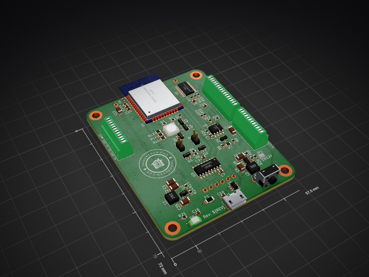
ESP32-Based Sensor PCB is an open-source printed circuit board by blazjerman, from the blazjerman/ESP32-Based-Sensor-PCB repository on GitHub, published under the MIT licence. It is a 2-layer board of 57.5 × 72 mm with 77 parts on 91 nets, routed with 434 tracks and 200 vias.
It is built around the CH340C, ESP32-WROOM-32E and THVD1400DRL, with the TLV62569DBVR-TP, TEMT6000X01 and USBLC6-2SC6-ES among its other parts. Its parts include 26 resistors, 17 capacitors, 9 connectors, 7 ICs and 6 transistors. It belongs with the sensors and measurement boards and the ESP32 boards of this library.


This ESP32-based sensor board is designed for various sensing and communication applications. It includes multiple integrated components such as light sensors, an I2C multiplexer, an RGB LED, RS485 communication, UART, and more. Below is a breakdown of the board’s features and how to interface with it.
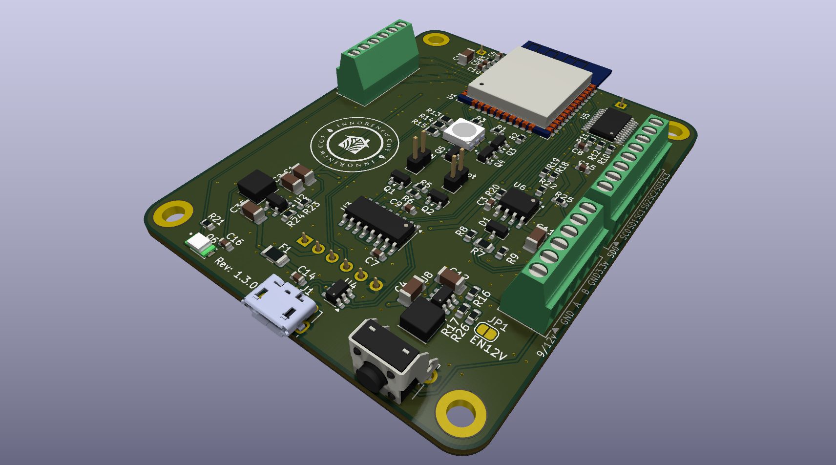
A software folder is included with example code for the Arduino IDE and ESP-IDF to test the board’s functionality. The folder contains examples for all features, making it easy to verify the hardware setup and operation.
| Component | ESP32 Pin | Notes |
|---|---|---|
| Light Sensor | IO35 | 3.3V, 10kΩ pull-down resistor |
| I2C Multiplexer | IO21 (SDA) / IO22 (SCL) | Address 0x70 |
| 9/12V Booster | IO19 | Enable pin |
| RS485 (MAX3485) | IO17 (DI) / IO16 (RO) / IO18 (RE/DE) | Terminal block labeled A & B |
| External UART | IO25 (TX) / IO26 (RX) | Direct ESP32 connection |
| Sound Sensor | IO12 (RX) / IO14 (TX) | RT-ZS-BZ-* sensor |
| RGB LED | IO13 (Red) / IO02 (Green) / IO32 (Blue) | Controlled via PWM |
| General Terminal | IO33 | Labeled "GP" |
| Button | I04 | pull down |
For updates or additional library formats, visit SnapEDA.
| Qty | Value | Footprint | References |
|---|---|---|---|
| 13 | 10k | Resistor_SMD:R_0603_1608Metric | R1, R2, R3, R4, R5, R6, R10, R11, R12, R20, R21, R22, R25 |
| 10 | 0.1uF | Capacitor_SMD:C_0603_1608Metric | C3, C5, C6, C7, C8, C9, C10, C14, C15, C16 |
| 5 | MMBT3904 | Package_TO_SOT_SMD:SOT-23 | Q1, Q2, Q3, Q4, Q5 |
| 4 | 10u | Capacitor_SMD:C_1206_3216Metric | C1, C2, C11, C13 |
| 4 | ~ | MountingHole:MountingHole_3.2mm_M3_DIN965_Pad | H1, H2, H3, H4 |
| 3 | 4.7u | Capacitor_SMD:C_1206_3216Metric | C4, C12, C35 |
| 3 | 680 | Resistor_SMD:R_0603_1608Metric | R8, R9, R19 |
| 2 | 100 | Resistor_SMD:R_0805_2012Metric | R14, R15 |
| 2 | 120 | Resistor_SMD:R_0805_2012Metric | R7, R13 |
| 2 | 205k | Resistor_SMD:R_0603_1608Metric | R16, R18 |
| 2 | Screw_Terminal_01x06 | TerminalBlock:TerminalBlock_Xinya_XY308-2.54-6P_1x06_P2.54mm_Horizontal | J4, J6 |
| 2 | ~ | Connector_PinSocket_2.54mm:PinSocket_1x01_P2.54mm_Vertical | J10, J11 |
| 1 | 10uH | Inductor_SMD:L_Sunlord_SWPA4020S | L2 |
| 1 | 15k | Resistor_SMD:R_0603_1608Metric | R24 |
| 1 | 1A | Fuse:Fuse_1206_3216Metric | F1 |
| 1 | 2.2uH | Inductor_SMD:L_Sunlord_SWPA4020S | L1 |
| 1 | 20k | Resistor_SMD:R_0603_1608Metric | R17 |
| 1 | 51k | Resistor_SMD:R_0603_1608Metric | R26 |
| 1 | 68k | Resistor_SMD:R_0603_1608Metric | R23 |
| 1 | Boot | Connector_PinHeader_2.00mm:PinHeader_1x02_P2.00mm_Vertical | J13 |
| 1 | CDSOT23-SM712 | Package_TO_SOT_SMD:SOT-23 | D1 |
| 1 | CH340C | Package_SO:SOIC-16_3.9x9.9mm_P1.27mm | U3 |
| 1 | EN | Connector_PinHeader_2.00mm:PinHeader_1x02_P2.00mm_Vertical | J12 |
| 1 | ESP32-WROOM-32E | RF_Module:ESP32-WROOM-32E | U1 |
| 1 | LOGO | LOGO | G*** |
| 1 | LTST-G563EGBW | LTST-G563EGBW:LED_LTST-G563EGBW | D7 |
| 1 | SW_Push | Button_Switch_THT:SW_Tactile_SPST_Angled_PTS645Vx39-2LFS | SW1 |
| 1 | Screw_Terminal_01x08 | TerminalBlock:TerminalBlock_Xinya_XY308-2.54-8P_1x08_P2.54mm_Horizontal | J2 |
| 1 | SolderJumper_2_Open | Jumper:SolderJumper-2_P1.3mm_Open_RoundedPad1.0x1.5mm | JP1 |
| 1 | TCA9548APWR | Package_SO:TSSOP-24_4.4x7.8mm_P0.65mm | U5 |
| 1 | TEMT6000X01 | TEMT6000X01:TRANS_TEMT6000X01 | Q6 |
| 1 | THVD1400DR | Package_SO:SOIC-8_3.9x4.9mm_P1.27mm | U6 |
| 1 | TLV61046ADBVR | Package_TO_SOT_SMD:SOT-23-6 | U8 |
| 1 | TLV62569DBVR | Package_TO_SOT_SMD:SOT-23-5 | U2 |
| 1 | USBLC6-2SC6-ES | Package_TO_SOT_SMD:SOT-23-6 | U4 |
| 1 | USB_B_Micro | Connector_USB:USB_Micro-B_Molex-105017-0001 | J1 |
| 1 | ~ | Connector_PinSocket_2.54mm:PinSocket_1x06_P2.54mm_Vertical | J9 |
It measures 57.5 × 72 mm and has 2 copper layers, 1.6 mm thick.
77 parts, built around the CH340C, ESP32-WROOM-32E, THVD1400DRL and TLV62569DBVR-TP. The full list of its parts is on this page, with links to each part's symbol and footprint where PCBKit's library has them.
From the blazjerman/ESP32-Based-Sensor-PCB repository on GitHub, at the commit this page was made from: the board is ESP32-Based Sensor PCB.kicad_pcb and its schematic 3.3V_buck.kicad_sch. PCBKit opens the board in the browser, with nothing to install.
Its repository publishes it under the MIT licence: you may reuse it on that licence's terms (keep the author's notice, and for a copyleft licence share your changes alike).
embeddedos-org/eCAD-Hardware-Products
Hardware designs + EE docs + Board datasheets of Multiple products

ssjrocks/cyd-obd-adapter
Open low-level OBD-II adapter: ESP32 with HS-CAN, single-wire CAN, flex CAN, 2x K-line, L-line and pin voltage probes, exposed over BT Classic, BLE, WiFi and USB as a raw proxy. KiCad 10, JLCPCB-ready.

nushackers/hnr26-badge-quacknroll
Hack&Roll 2026 "Quack & Roll" badge source files, for both hardware and firmware

PTR-projects/PTR_mini_hardware
Welcome to the KPPTR-hardware repository! This repository contains the design files for the hardware components used in the KPPTR project.

hiralsinghal/USB-Hub
This is a USB hub. It has a USB-C port to connect to the device. It has two USB-A ports and two USB-C ports, which can be used for connecting more devices as it allows you to increase the number of ports available.

PTR-projects/PTR_micro_hardware
Welcome to the KPPTR-hardware repository! This repository contains the design files for the hardware components used in the KPPTR project.


albertoboffi-PERSONAL/fra-clock
A one-off gift PCB designed in KiCad 10: an ESP32 clock with a ring of 180 WS2812B‑2020 LEDs, a photo printed in exposed copper on the front, two Makerverse 8 Ω / 5 W speakers driven by two MAX98357A I²S amplifiers…