2 layers40 × 20 mm

 blark/a500plus-chipram-expansion32
A 1MB chip RAM expansion for the A500+
A500plus chipram expansion is an open-source printed circuit board by blark, from the blark/a500plus-chipram-expansion repository on GitHub. It is a 2-layer board of 41.3 × 51.8 mm with 13 parts on 45 nets, routed with 675 tracks and 82 vias.
Its parts include 7 capacitors, 2 ICs, 1 resistor, 1 connector and 1 switch. It belongs with the retro computing and games boards of this library.
This is a 1MB chip RAM expansion designed for the Amiga 500+ in KiCad.
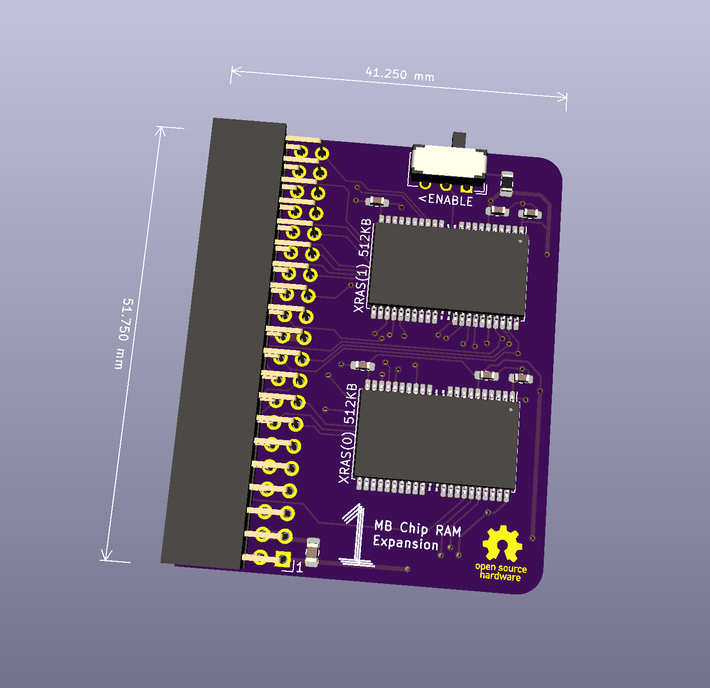
It is in the experimental phase, but I've assembled it and it appears to be working great. However, you've been warned!
Small (42mmx52mm), simple design using only a 40 pin (2x20) female 2.54mm connector. The remaining pins are for the RTC which is on-board the A500+, so they are unecessary for RAM expansion. This makes it possible to use a 40 pin connector, which is cheaper and easier to find.
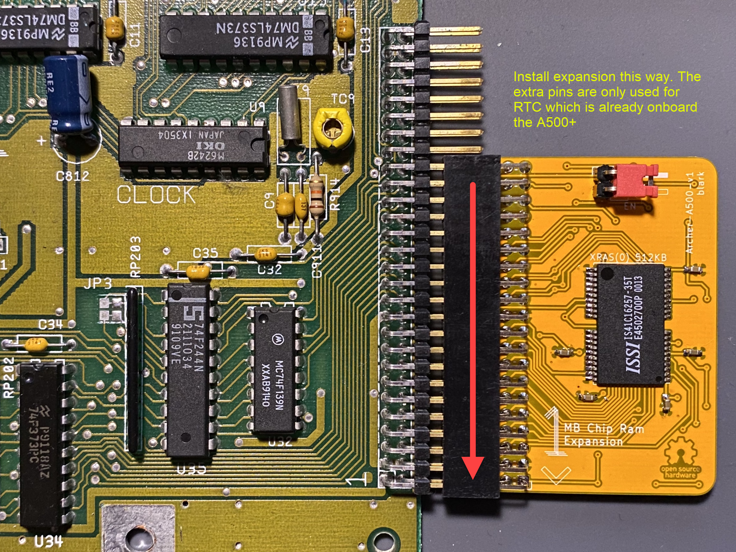
WARNING: make sure you plug it in correctly see the install section below.
A PDF file of the schematic can be found in this repo.
I shared the design at Oshpark
| Designator | Description |
|---|---|
| J1 | 40P (20x2) female header 2.54mm |
| J2 | 1x DPDT Sub-Miniature Slide switch (9x4x3.5mm, easily found on Ebay) |
| U1-U2 | IS41C16257-35T 4mbit DRAM (256 x 16) |
| C1-C6 | 100nF 603 SMD capacitor |
| C7 | 10uF 805 SMD capacitor |
| R1 | 10K 805 SMD resistor |
Be careful during install to match pin 1 on the expansion with pin 1 on the A500+ memory expansion port! Here's an image of how it should be installed:
The parts library I've included (and expanded upon) in this repo is "borrowed" from Kai Robinson check out his great projects!
| Qty | Value | Footprint | References |
|---|---|---|---|
| 6 | 100nF | Capacitor_SMD:C_0603_1608Metric_Pad1.05x0.95mm_HandSolder | C1, C2, C3, C4, C5, C6 |
| 1 | 10K | Resistor_SMD:R_0805_2012Metric_Pad1.15x1.40mm_HandSolder | R1 |
| 1 | 10uF | Capacitor_SMD:C_0805_2012Metric_Pad1.15x1.40mm_HandSolder | C7 |
| 1 | <ENABLE | Button_Switch_THT:SW_CuK_JS202011AQN_DPDT_Angled | SW1 |
| 1 | A500 MEM EXP | Connector_PinHeader_2.54mm:PinHeader_2x20_P2.54mm_Horizontal | J1 |
| 1 | XRAS(0) 512KB | a500plus-chipram-expansion:TSOP-II-40 | U1 |
| 1 | XRAS(1) 512KB | a500plus-chipram-expansion:TSOP-II-40 | U2 |
The 12 most common of 13 parts.


samyk/magspoof
A portable device that can spoof/emulate any magnetic stripe, credit card or hotel card "wirelessly", even on standard magstripe (non-NFC/RFID) readers.

fossasia/pslab-scripts
Pocket Science Lab - Scripts for Sensor Experiments


willem-pennings/balancing-cube
A cube that balances itself in a corner or edge using reaction wheels

VoronDesign/Voron-Hardware
Cool Hardware designed by the Voron Design group

hoglet67/RGBtoHDMI
Bare-metal Raspberry Pi project that provides pixel-perfect sampling of Retro Computer RGB/YUV video and conversion to HDMI
It measures 41.3 × 51.8 mm and has 2 copper layers, 1.6 mm thick.
13 parts. The full list of its parts is on this page, with links to each part's symbol and footprint where PCBKit's library has them.
From the blark/a500plus-chipram-expansion repository on GitHub, at the commit this page was made from: the board is a500plus-chipram-expansion.kicad_pcb. PCBKit opens the board in the browser, with nothing to install.
Its repository states no licence, so its author keeps all rights: ask blark before reusing the design.