
2 layers10.4 × 13.3 mm
TPDD Cable 1
bkw777/TPDD_Cable
TTL-RS232 level-shifting cable for Tandy Portable Disk Drive
11 parts4CC-BY-SA-4.0

 bkw777/TPDD_Cable4
TTL-RS232 level-shifting cable for Tandy Portable Disk Drive
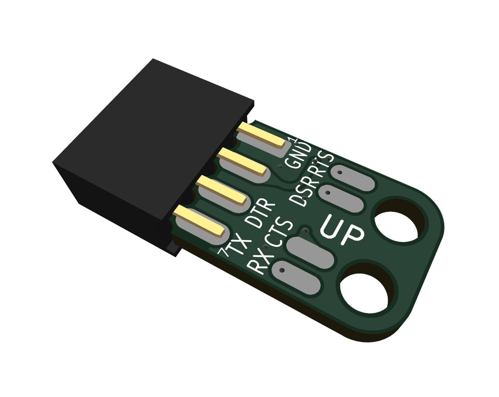
TPDD Cable is an open-source printed circuit board by bkw777, from the bkw777/TPDD_Cable repository on GitHub, published under the CC-BY-SA-4.0 licence. It is a 2-layer board of 10.3 × 15 mm with 11 parts on 11 nets, routed with 27 tracks and 10 vias.
It is built around the DTA114EKA. Its parts include 5 connectors and 3 transistors.
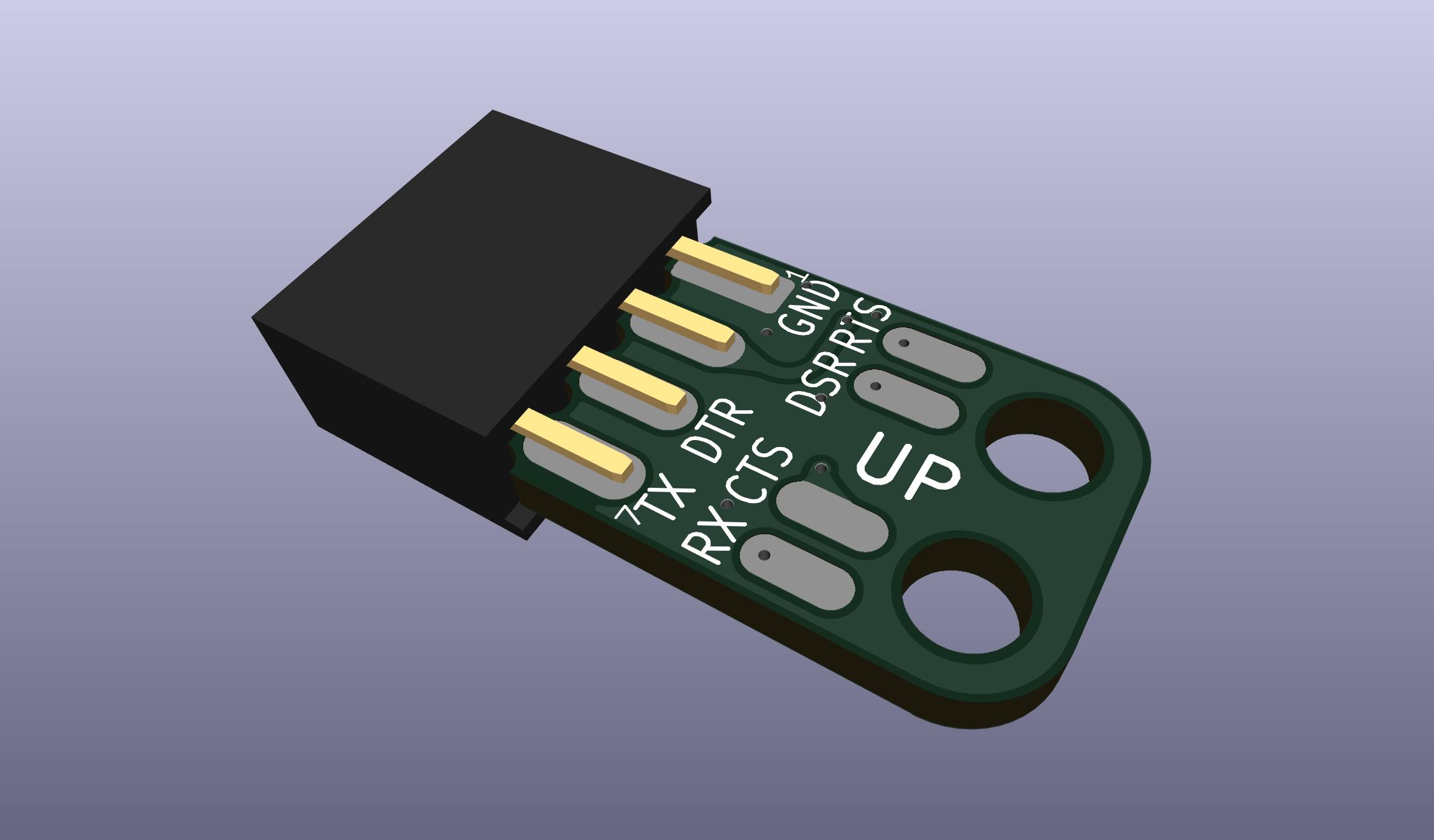
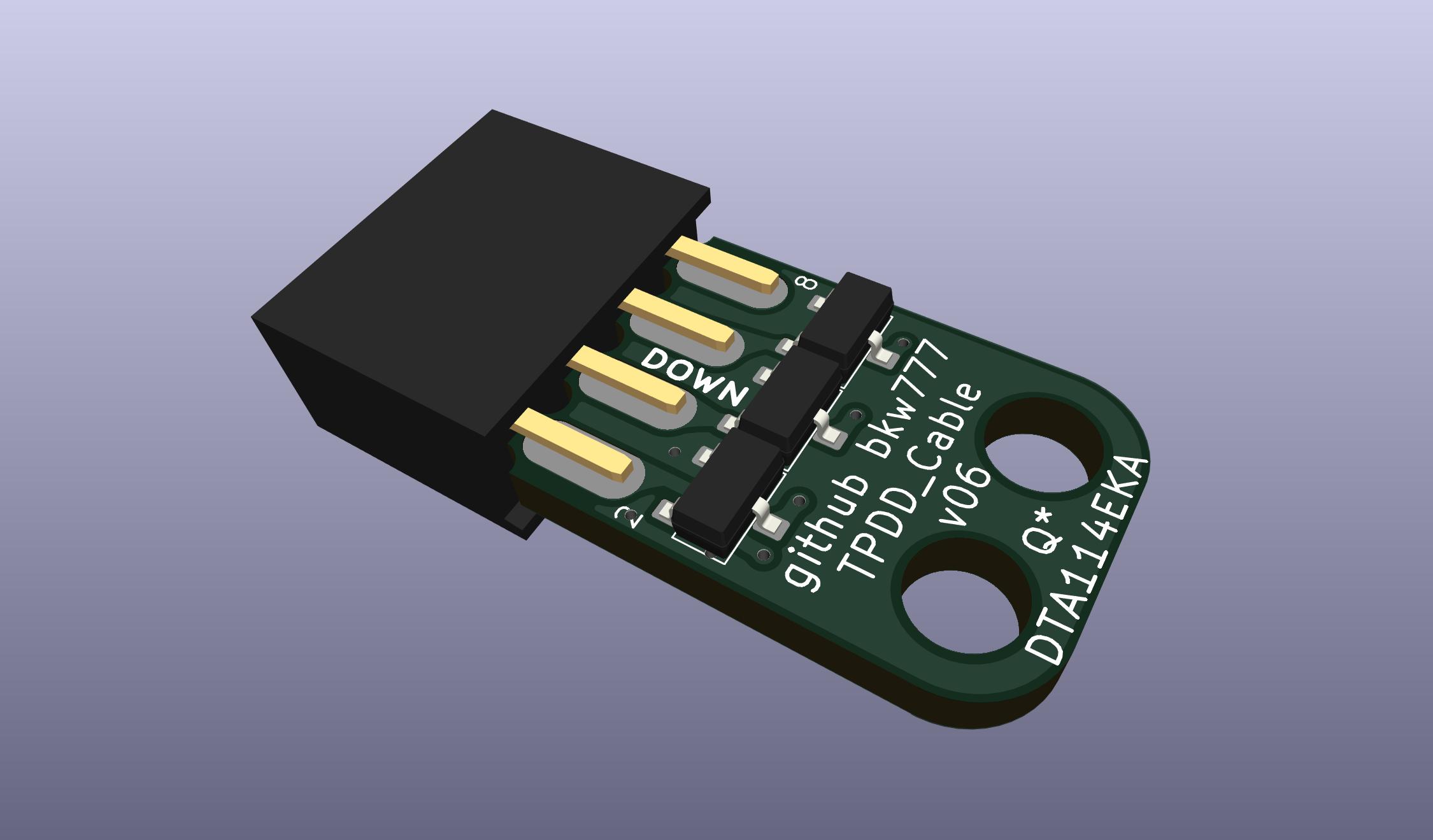
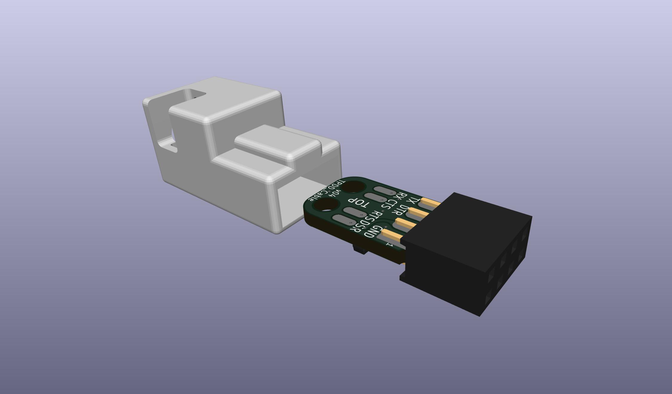
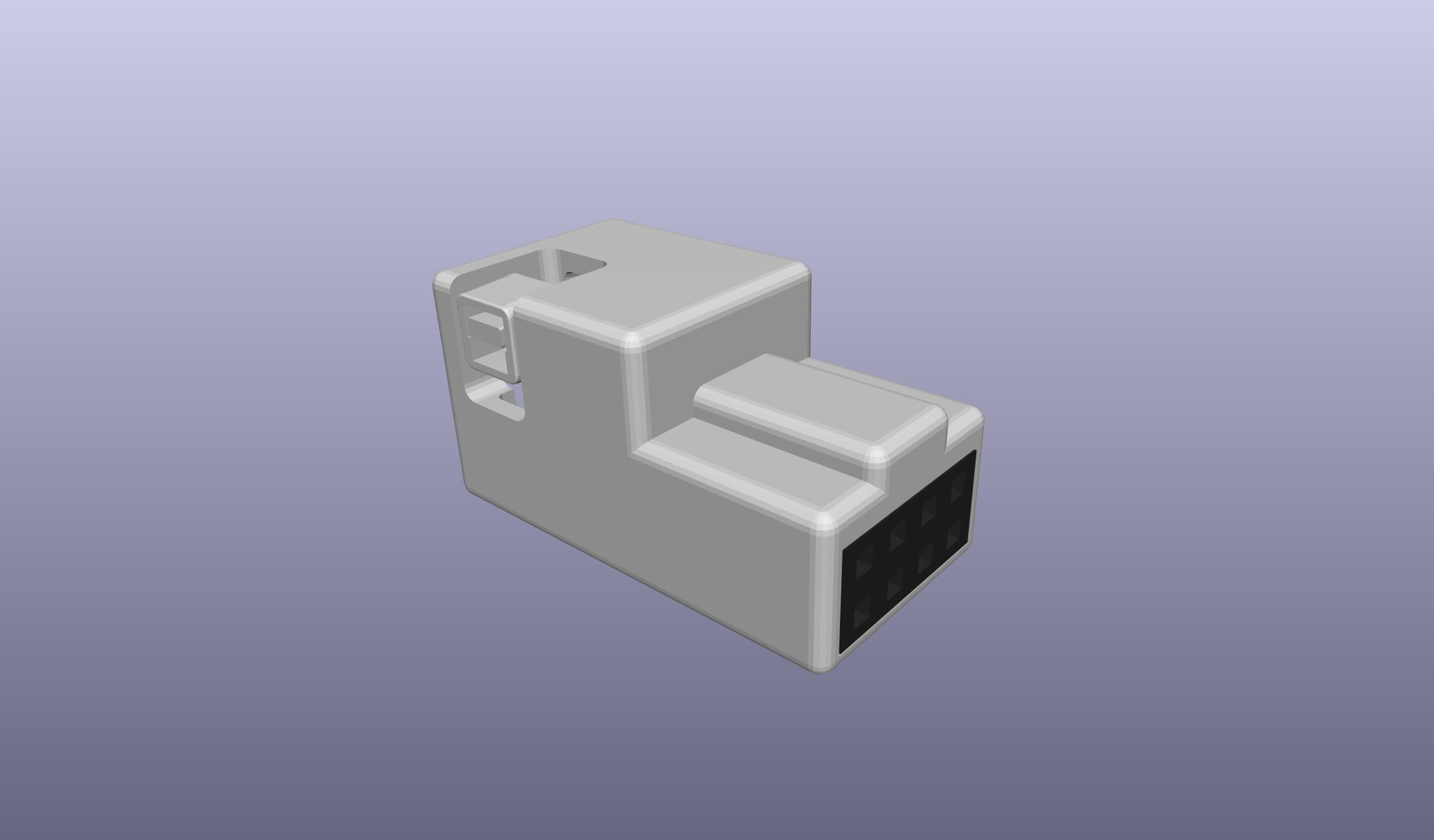
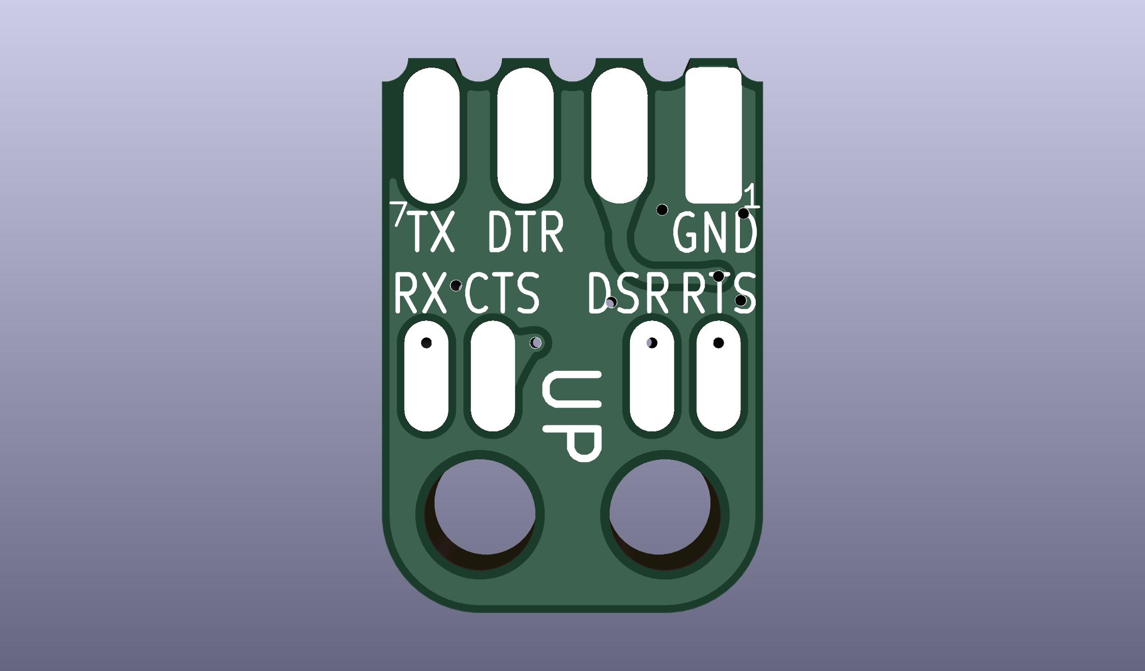
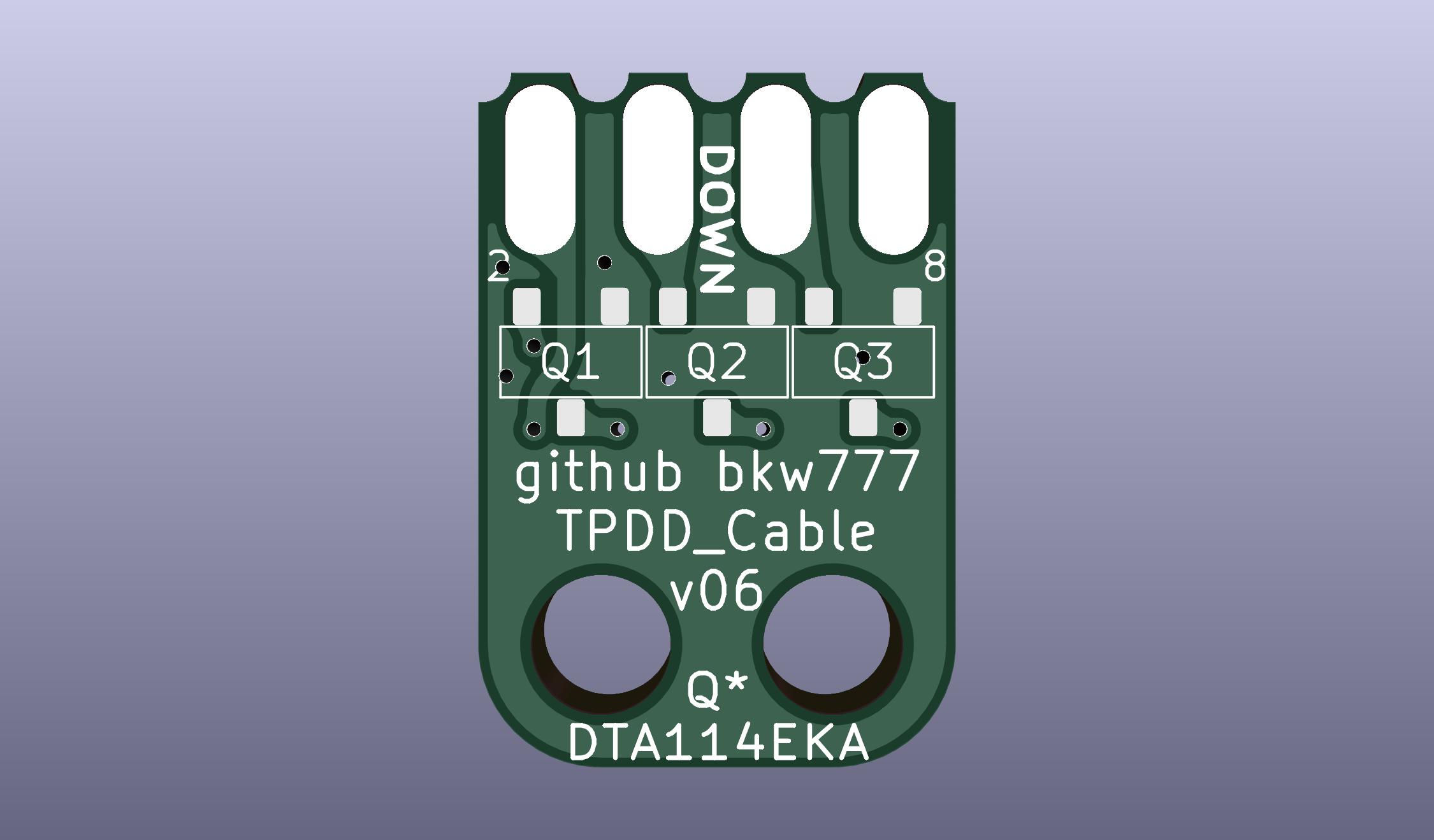
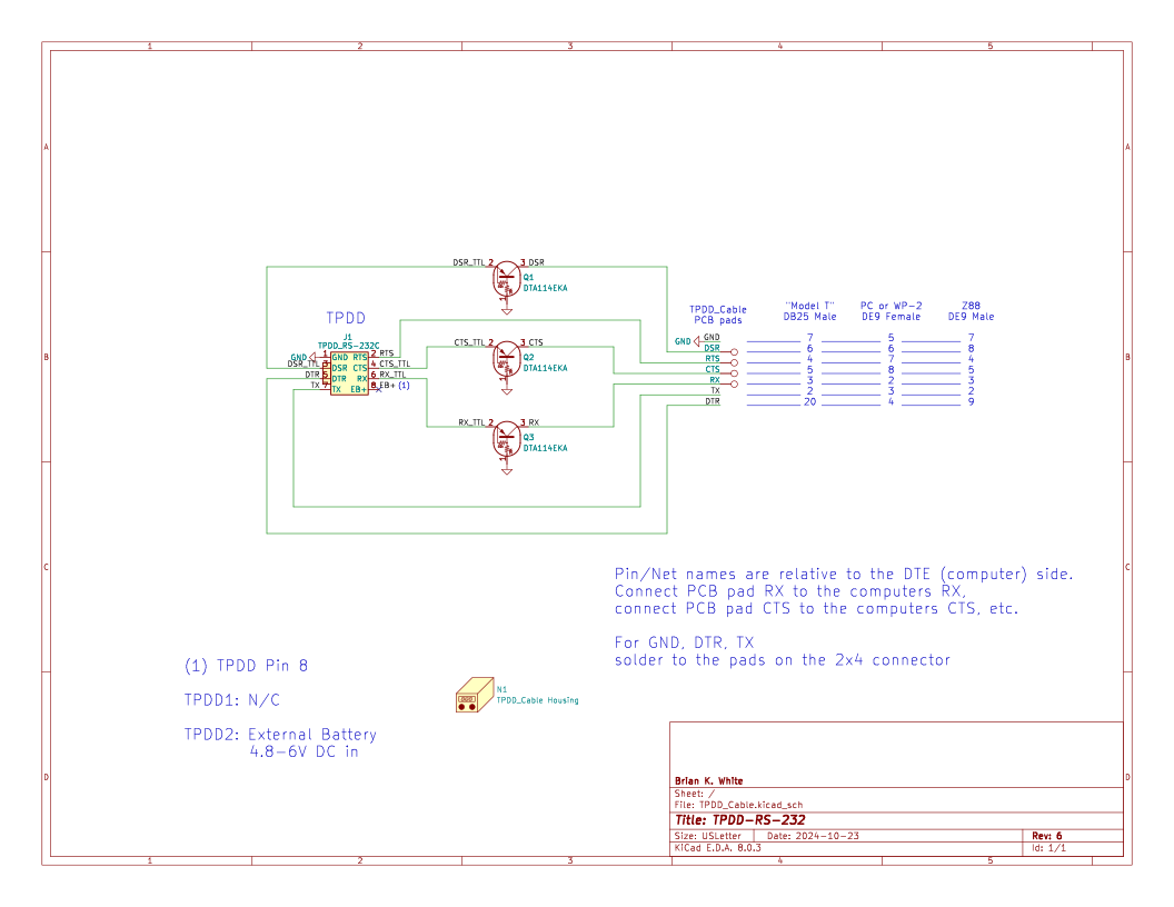
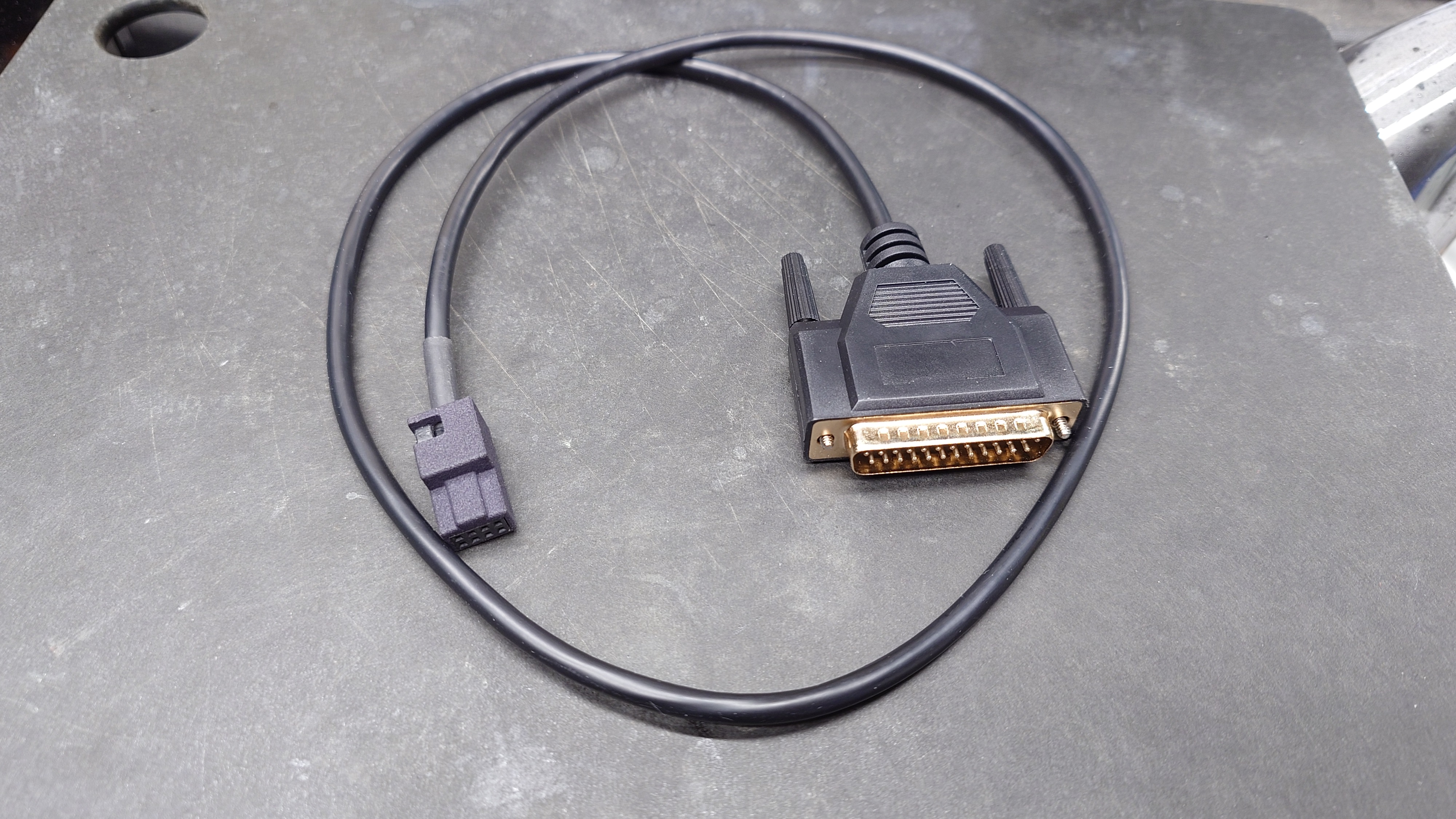
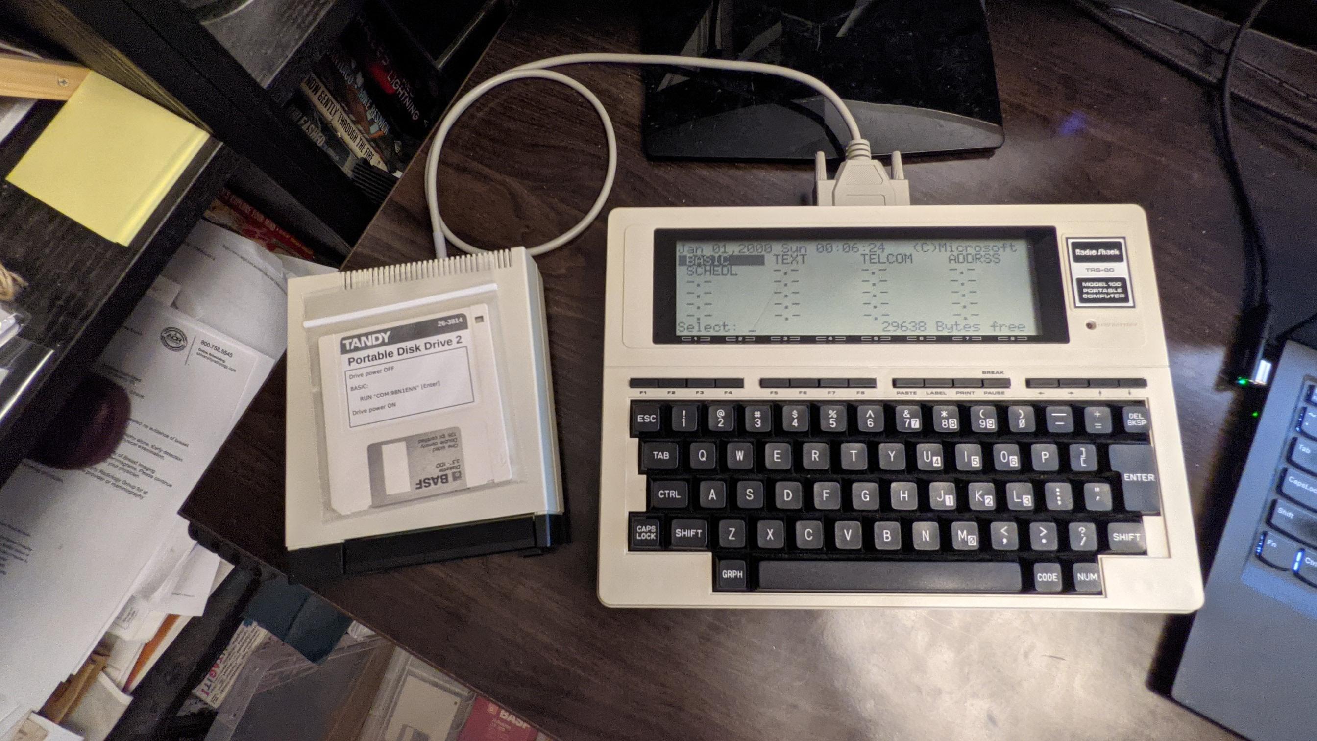
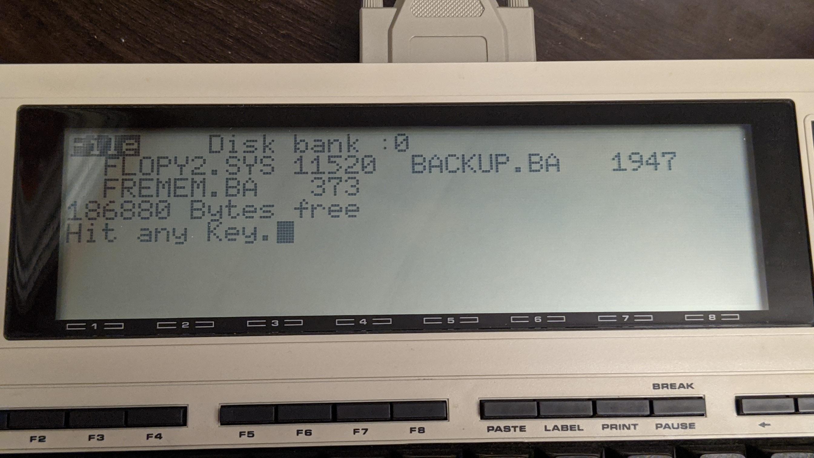
PCB & Housing (and solder jig): PCBWAY
BOM: DigiKey
The BOM includes a grey cable. This black cable can be substituted if you want.
If you want to make 2 cables, one for Model 100 and one for PC/WP-2, then double the BOM components except for the cable, and cut the cable in half right in the middle.
Otherwise just cut off the 9-pin plug to make one longer cable for Model 100 and other KC-85 clones.
Cut the unwanted plug off the cable.
If building a Model 100 cable, cut off the 9-pin plug.
If building a PC/WP-2 cable, cut off the 25-pin plug.
If building both cables, cut the cable in half in the middle.
Strip off about 1 inch or 25mm of the cable jacket.
Also cut the foil shield and the bare wire short right at the end of the jacket.
Apply a bit of flux to the ends of the loose wires.
Load up the soldering iron with a ball of solder and touch the soldering iron to the end of each wire long enough for the insulation to shrink itself back about 1-2mm and tin the end of the wire at the same time. You only need about 1mm of wire exposed and it's not worth trying to actually strip the insulation the normal way. Just heat the very tip end and it will melt and shrink itself back the perfect amount and the wire will end up tinned as well.
Insert the cable into the round opening on the housing and push the cable all the way through the housing and slide the housing about a foot back from the end of the cable.
Thread a 1 to 1-1/2 inch (25-30mm) piece of heatshrink onto the cable and slide back to the housing.
Don't shrink it.
Print the wire color worksheet.
Put a DMM into continuity mode.
Use a jumper wire or meter lead with an alligator clip to grab one of the wires and connect to one lead of the DMM.
Probe with the other meter lead to touch each pin on the DB25 to find which pin that wire goes to.
Write the color of the wire for that pin number on the worksheet.
Repeat for all wires.
Cut the un-used wires short.
For the exact cable in the BOM and probably most cables, there will be 3 wires with no place on the PCB: a bare wire connected to both the DB25 shell and pin 1, a wire on pin 8, and a wire on pin 22.
Cut all of those as short as possible right at the end of the cable jacket.
Sand the edge of the pcb as neccessary to flatten any pointy bits left from the edge routing. The front edge is supposed to be castellated, so don't try to grind those away, but the front edge is supposed to be straight, so sand flat anything that sticks out from the rest.
Blunt or chamfer the rim of the drill holes on the bottom side of the pcb (the side with the chips). Use a countersink bit if you have one, or a drill bit. If nothing else a phillips screwdriver will barely work. You just want to blunt the sharp edge of the hole so the zip tie can be pulled through, don't grind a deep chamfer.
Solder the transistors onto the pcb.
Insert the pcb and the 2x4 connector into the solder jig.
Face up or down doesn't matter.
Solder the 4 exposed pins on the 2x4 connector.
Remove the pcb from the jig and solder the other 4 pins on the 2x4 connector.
The signal names on the PCB are relative to the computer, aka the DTE side.
Ex: The pad labelled RTS on the PCB connects to the computers RTS.
Follow your worksheet to match wire colors to the pads on the PCB.
Add solder to the 4 oval wire pads first so that you only need to touch the wire to solder it.
Start with the cable pointing the "wrong" way on the pcb, with the ends of the wires pointing towards the zip tie holes, ie the opposite direction from how it must be in the end, and solder the 4 wires that go to the 4 oval pads.
Then fold the cable over and fish the remaining 3 wires in between the 4 soldered wires towards their respective pins on the 2x4 connector. Keep all 3 of these wires inside of the first 4, ie the 2 outside wires of the 1st 4 remain the outermost wires when done. It's annoying but results in the least pinching & crossing of wires later.
Wash all flux from the pcb and wires.
Clean the end of the cable with alcohol where the heat-shrink will go if not done already.
Slide the heat-shrink 2mm past the end of the end of the cable jacket, just enough to cover the unused cut wires and shielding, and shrink it. Don't leave any more heat shrink in front of the jacket than necessary to cover the cut wires. You need to push the cable into the plug body as far as possible later, and excess heat-shrink will prevent the cable from inserting as far as it could.
Make sure the transistors face DOWN, and the polarity key points UP.
Slide the housing up over the pcb, or in other words pull the pcb into the housing.
The heat-shrink will want to catch on the front edge of the housing on the way in, and also on an internal lip at the rear of the housing on the way out.
Squeeze and angle the cable to get the heat-shrink started into front of the housing, and pull the cable on the back 45 degrees up towards the top of the housing before pulling the heat-shrink all the way through so the heat-shrink doesn't catch on a lip at the bottom rear inside the housing.
Regardless, if the heat-shrink gets dug up on the way through, just heat it again and it will smooth back out.
Once the pcb is all the way in, push the cable forward into the housing as far as possible while holding the pcb in with a finger over the front.
Make sure the end of the jacket goes past the zip tie area.
Use pliers to put a small extra bend at the very tip of the zip tie, just the last 1-2mm right at the tip, in the same direction it's already bent (the direction it will bend to wrap around the cable).
Insert the zip tie pointing down into the one exposed hole in the pcb you can see, and push in with needle nose pliers until the tip comes out the top. Then you should be able to pull the tie out some more, thread it through the head and pull it the rest of the way. Stop before going all the way tight and jam the cable in as far as possible before cinching down tight.
If you didn't chamfer or blunt the bottom side of the drill holes, then you may have to push the zip tie in with pliers the whole way instead of pulling.
The zip tie does double duty. It both clamps the cable to the pcb and is also what locks the pcb into the housing so the pcb can't pull back out the front.
Once you have tested the cable and are sure the connections are correct, it would be best to inject some glue (C-A/super glue, vynil e6000/goop/etc) into the housing to immobilize the wires and to prevent the cable from working back out of the zip tie. If you're careful you could probably use hot glue by applying some just before inserting the cable, but you'll need to be careful to definitely get some on the pcb all the way back between the holes so that it grabs the heat shrink well, yet not plug up the holes where you will need to push the zip tie through.
For convenience, the tables below show the wire colors for the specific cables linked here.
If you buy one of these exact specific cables, then your cable should match one of the tables below, but still double-check the wire colors to pin numbers before soldering.
If you use any other cable that isn't specifically from one of the links here, then ignore the colors in the tables below and map out your cables wire colors yourself with a DMM continuity beeper and one of the printable worksheets below.
The grey cable in the BOM, and the alternative black cable, has both a DB25M on one end and a DE9F on the other end, so you can use the same BOM to make either a "Model T" cable, or a PC cable, or one of each if you double up the other components.
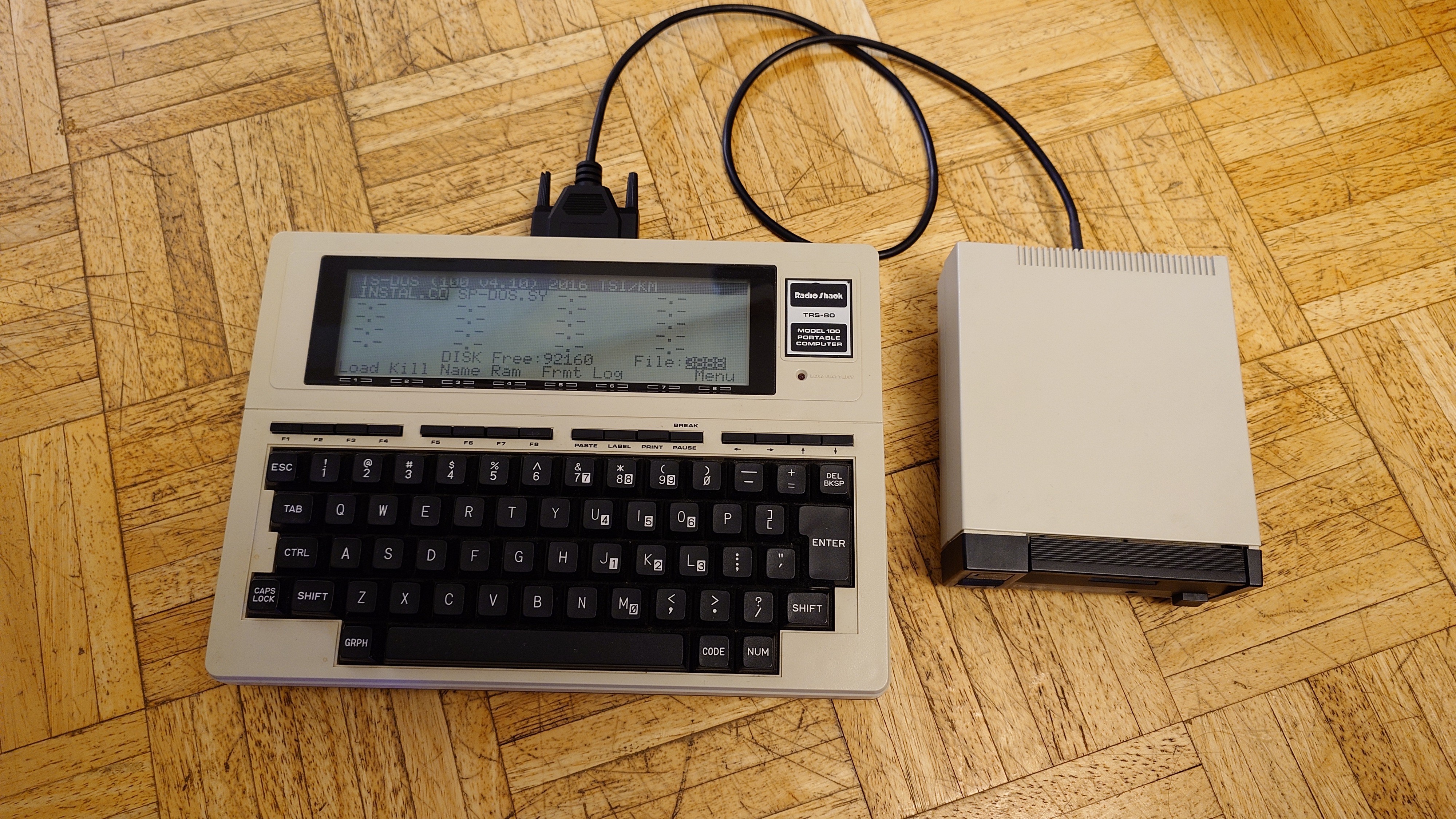
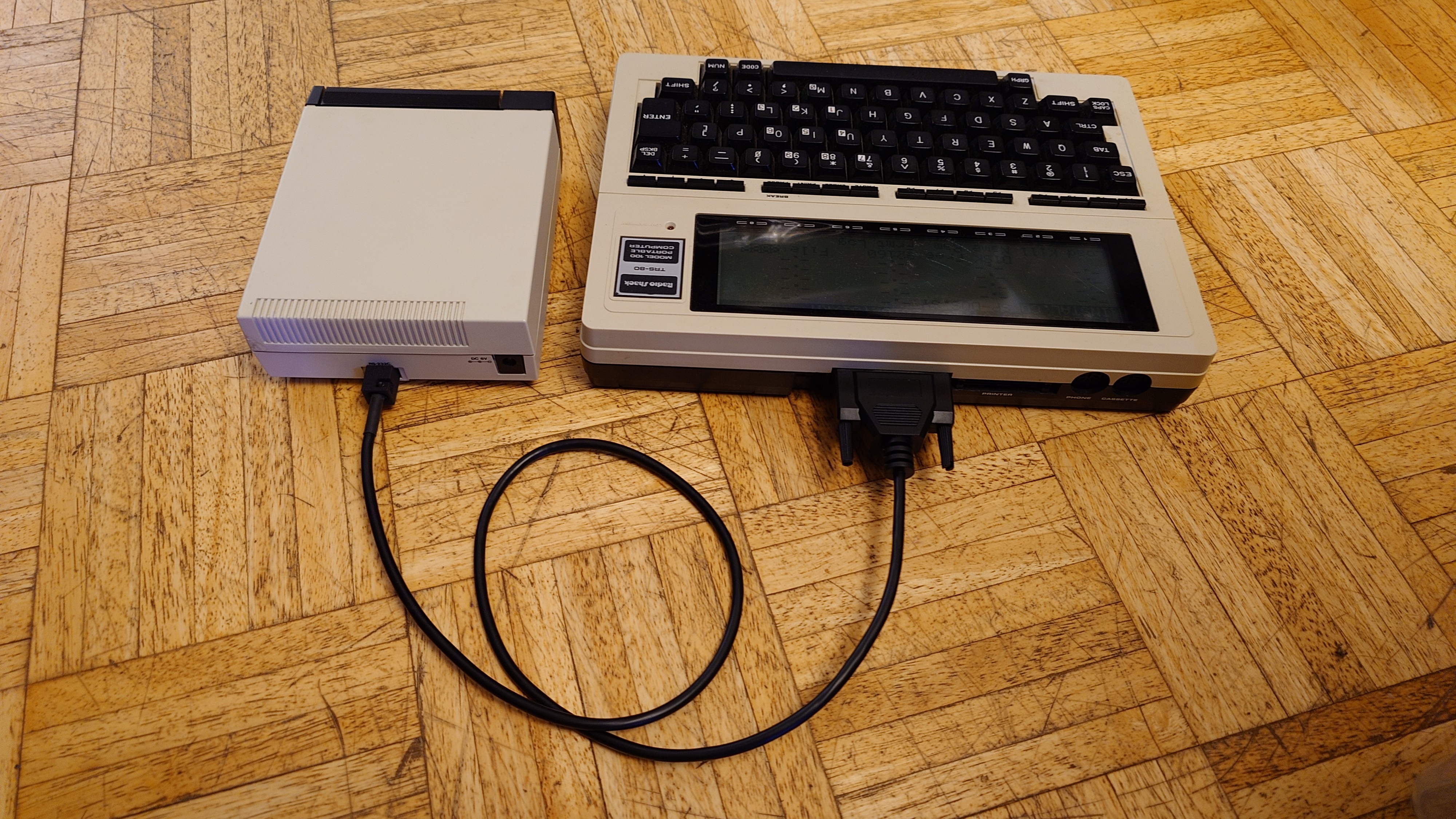
This is the standard version of the cable that replicates the cable that originally shipped with the TPDD and TPDD2.
The cable in the BOM supports this option.
It supports at least the following machines:
Any other machine with a female DB25 DTE RS-232 port. The female part is unusual but some other early machines besides these did have it this way also.
PRINTABLE WIRE COLOR WORKSHEET for KC-85 CLONES
| PCB PAD | GREY CABLE | BLACK CABLE | DB25 PIN | ||
|---|---|---|---|---|---|
 | TX | Orange | Red | 2 | 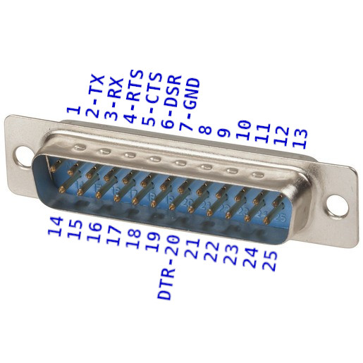 |
| RX | Red | Brown | 3 | ||
| RTS | Purple | Blue | 4 | ||
| CTS | Grey | Purple | 5 | ||
| DSR | Blue | Green | 6 | ||
| GND | Green | Yellow | 7 | ||
| DTR | Yellow | Orange | 20 | ||
To verify the final result, check the following with a DMM in Continuity and Diode modes.
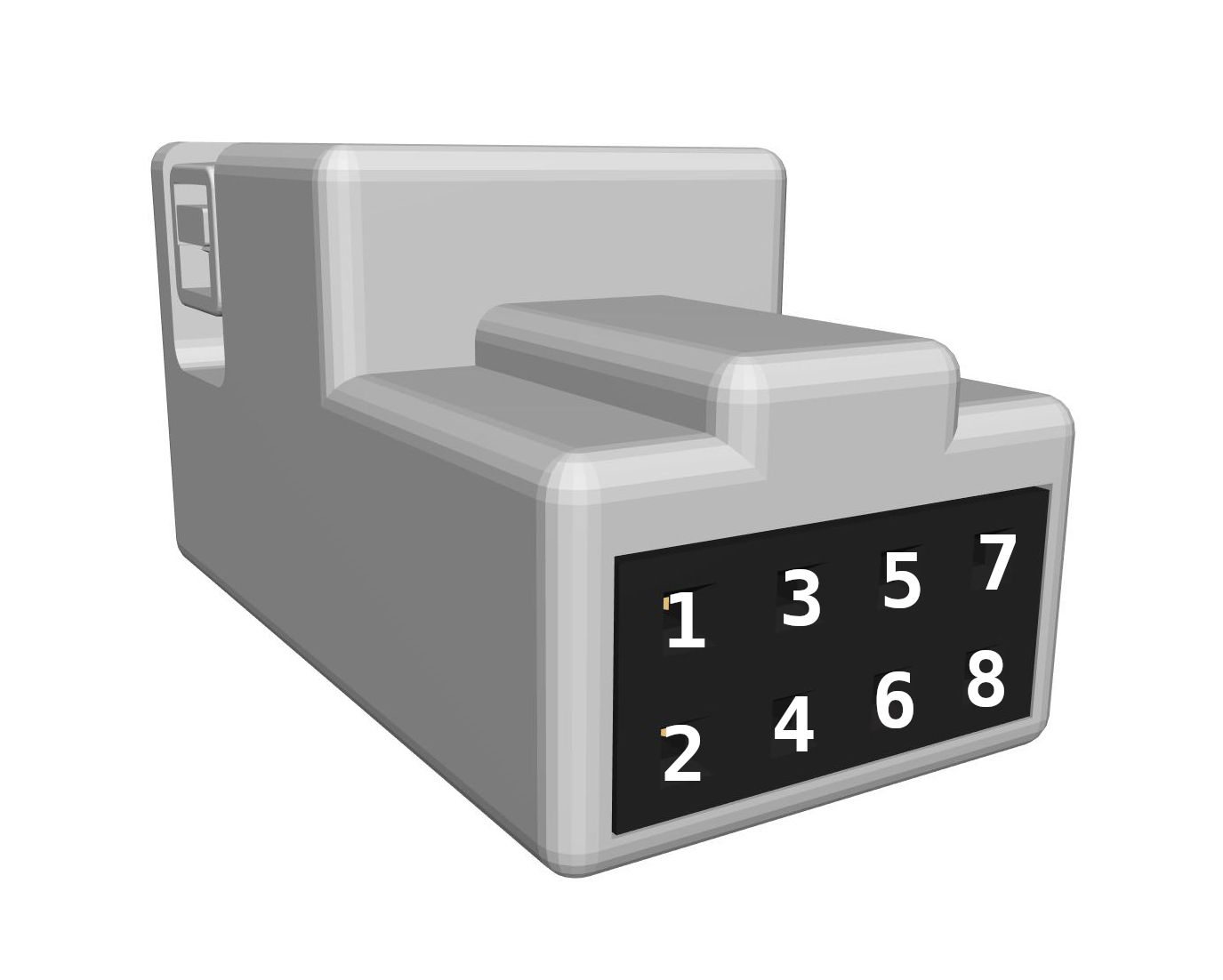 | BLACK | CONT | DIODE | RED | |
|---|---|---|---|---|---|
| 1 | BEEP | 7 | |||
| 2 | BEEP | 4 | |||
| 3 | 1.7v | 6 | |||
| 4 | 1.7v | 5 | |||
| 5 | BEEP | 20 | |||
| 6 | 1.7v | 3 | |||
| 7 | BEEP | 2 |
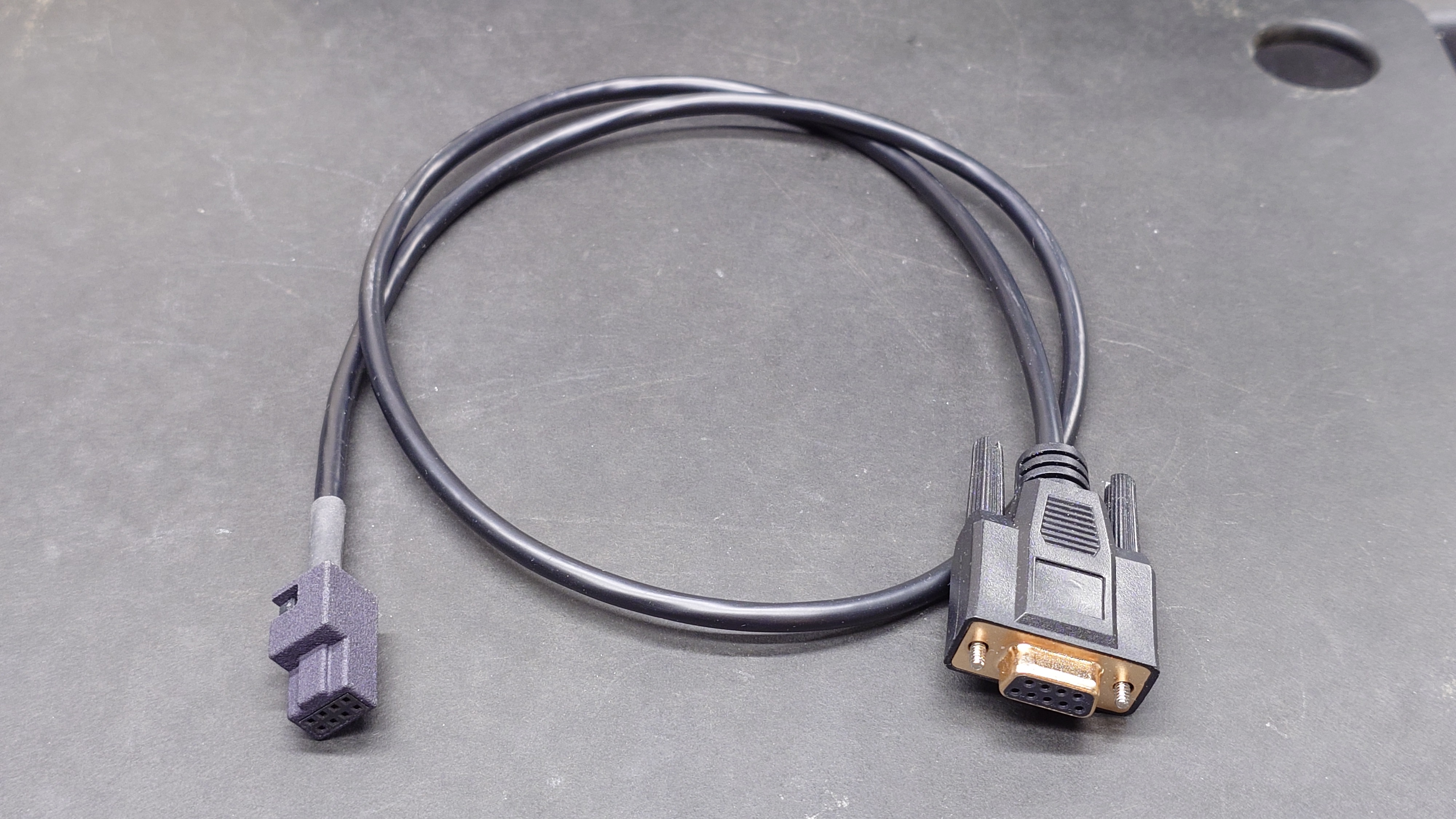
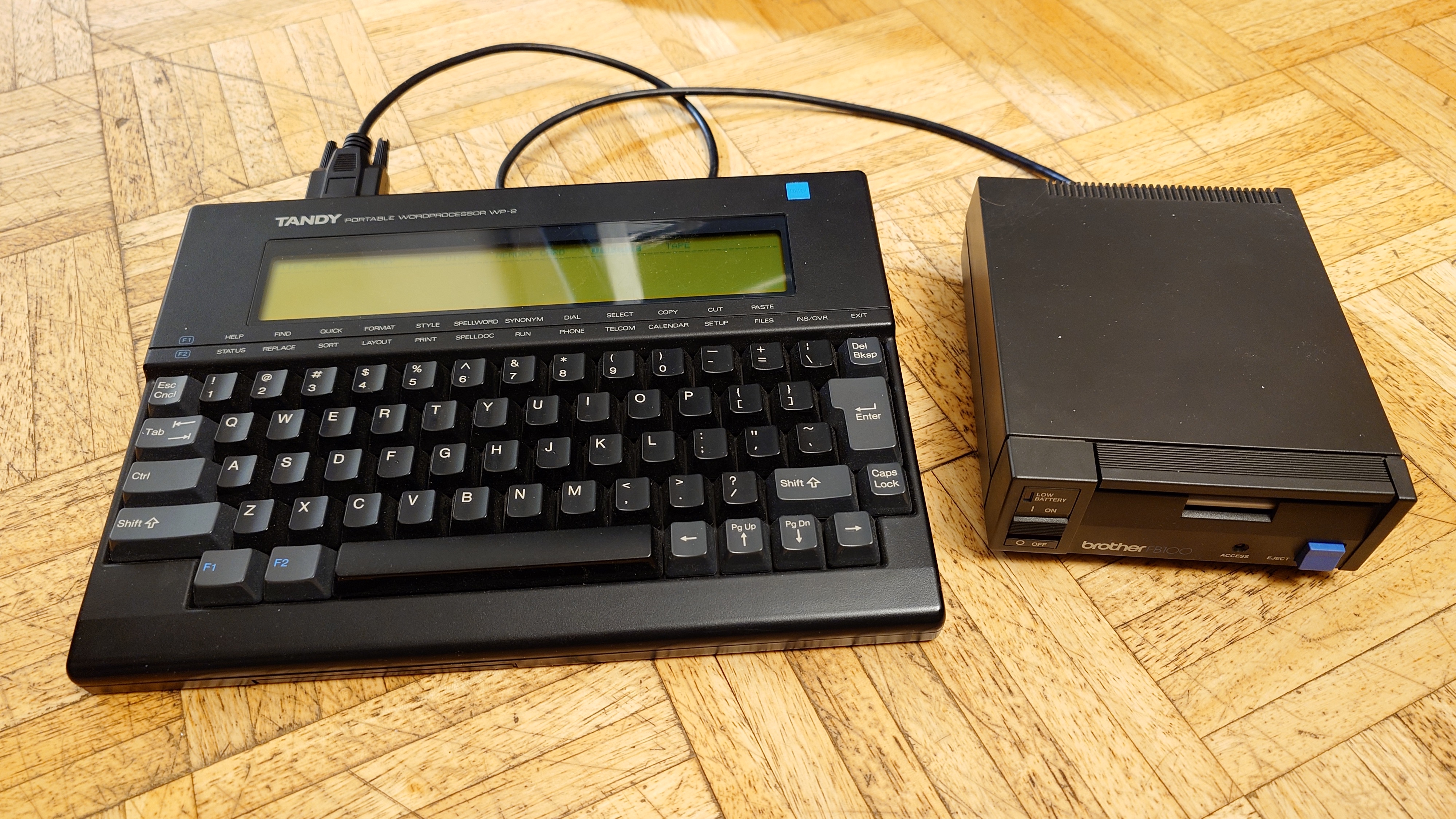
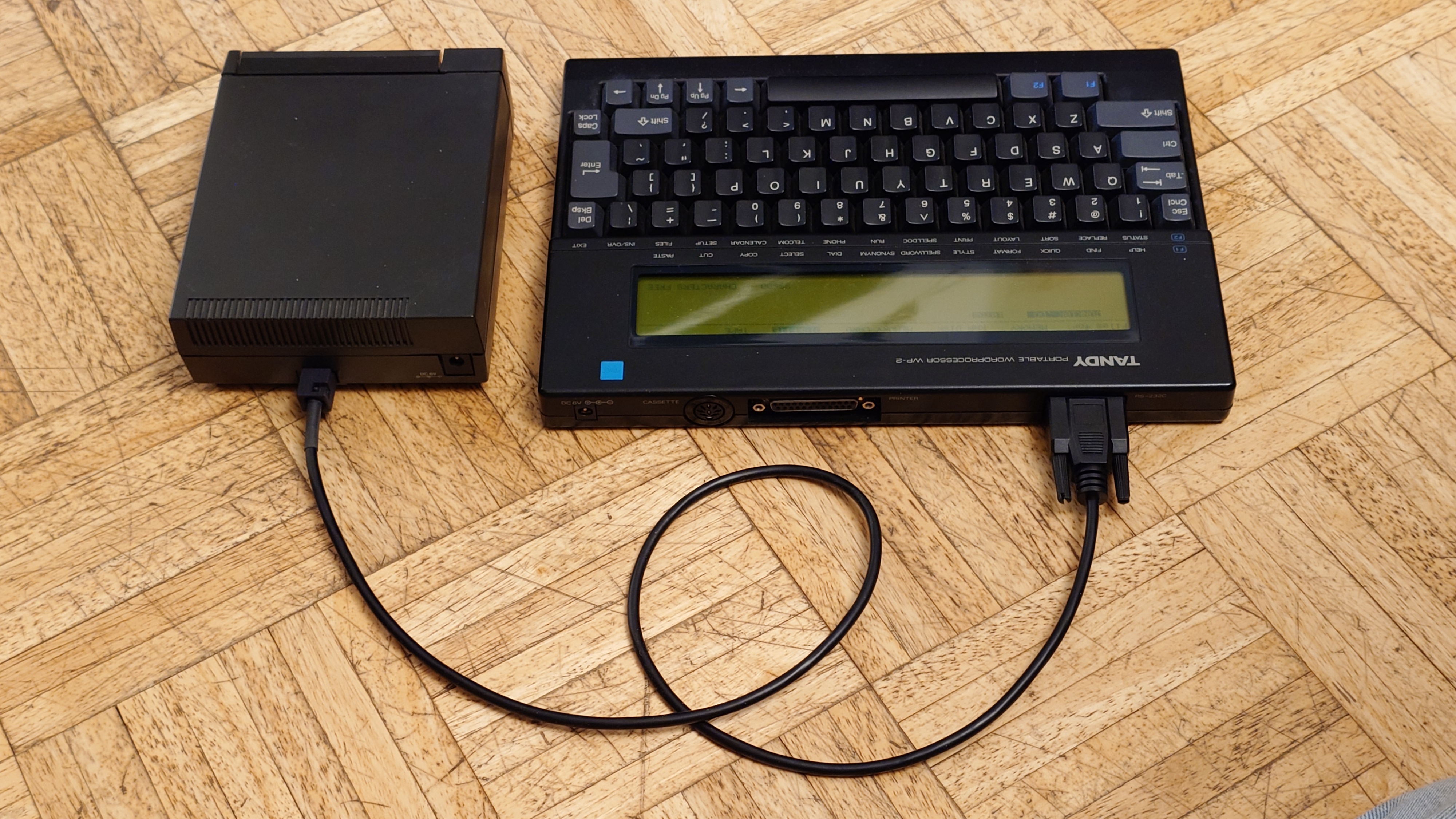
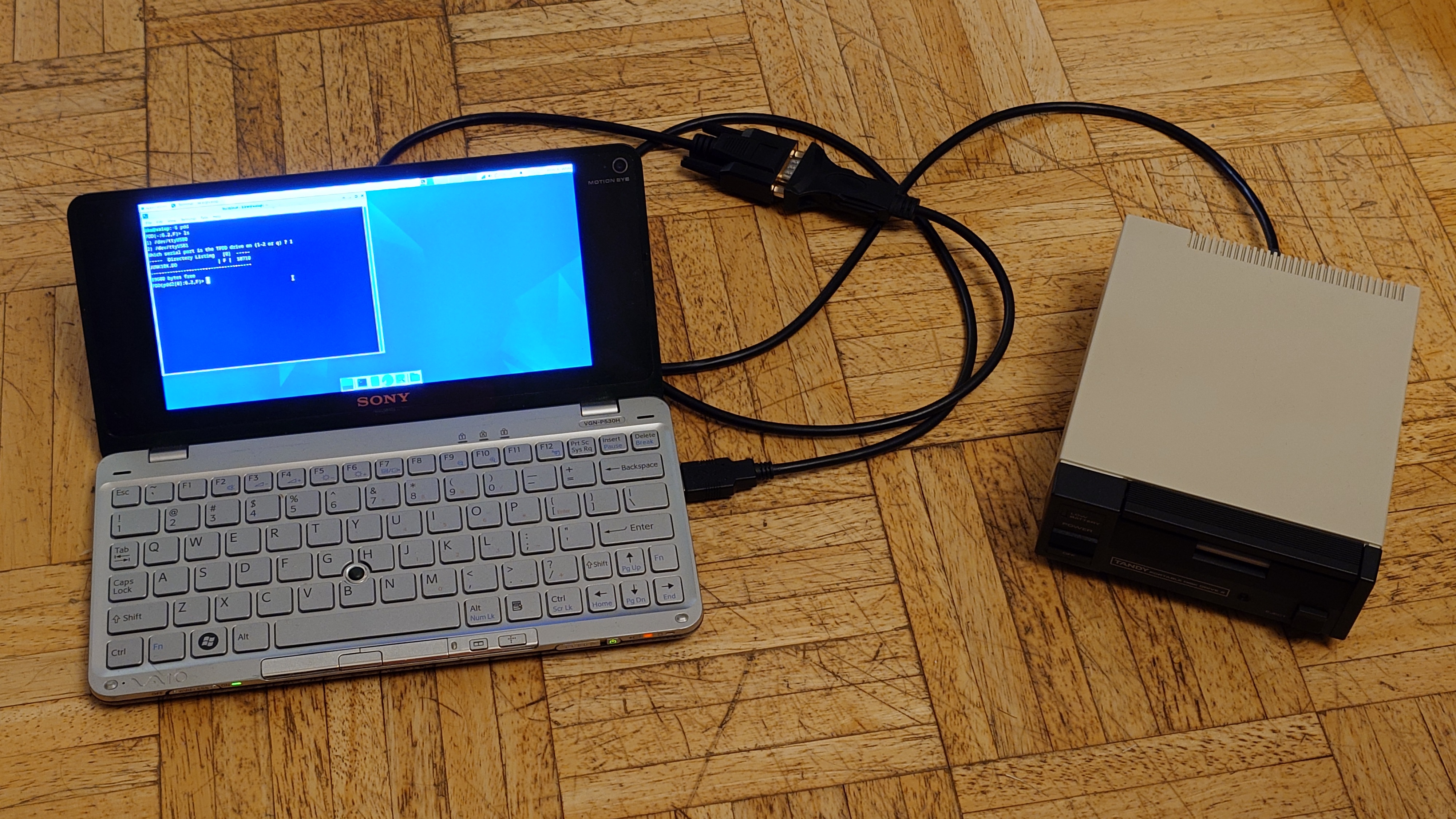
This version supports:
IE this is for connecting the TPDD directly to a PC, which is not something you usually need to do.
This cable is useful for using pdd.sh to take a raw disk image of a commercial disk or to re-create a disk from a disk image. You don't need this merely to copy normal files, but disks like the utility disks and the sardine dictionary disk are special and can't be copied any other way.
This is also useful if you have a Tandy WP-2 and want to use it's built-in TPDD support.
The cable in the BOM supports this option.
PRINTABLE WIRE COLOR WORKSHEET for PC/WP-2
| PCB PAD | DE9 PIN | ||
|---|---|---|---|
| RX | 2 | 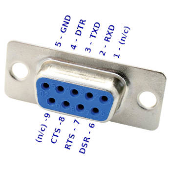 |
| TX | 3 | ||
| DTR | 4 | ||
| GND | 5 | ||
| DSR | 6 | ||
| RTS | 7 | ||
| CTS | 8 | ||
To verify the final result, check the following with a DMM in Continuity and Diode modes.
| BLACK | CONT | DIODE | RED | |
|---|---|---|---|---|---|
| 1 | BEEP | 5 | |||
| 2 | BEEP | 7 | |||
| 3 | 1.7v | 6 | |||
| 4 | 1.7v | 8 | |||
| 5 | BEEP | 4 | |||
| 6 | 1.7v | 2 | |||
| 7 | BEEP | 3 |
UNTESTED
The Cambridge Z88 RS-232 port has a non-standard pinout.
Do not connect this cable to anything but a Cambridge Z88.
The cable in the BOM does NOT support this option.
Delete the cable from the pre-loaded DigiKey cart, and add this one instead.
| PCB PAD | DE9 PIN | ||
|---|---|---|---|
| TX | 2 | 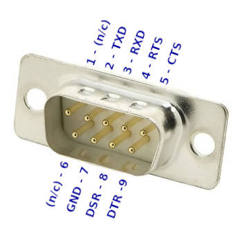 |
| RX | 3 | ||
| RTS | 4 | ||
| CTS | 5 | ||
| GND | 7 | ||
| DSR | 8 | ||
| DTR | 9 | ||
In the beginning, there was the Marty Goodman Document, and it was good.
More recently, Rick Shear has taken a new and very careful look at a real cable, and the Marty Goodman doc, and has probably identified the "mystery" components that Marty Goodman talks about. It looks right, and the circuit does indeed work.
Rick's initial post
Rick's follow-up
This cable uses the same transistors, but a different physical construction.
| Qty | Value | Footprint | References |
|---|---|---|---|
| 3 | DTA114EKA | 000_LOCAL:SC-59 | Q1, Q2, Q3 |
| 1 | CTS | 000_LOCAL:SMD_1.2x3 | P5 |
| 1 | DSR | 000_LOCAL:SMD_1.2x3 | P6 |
| 1 | RTS | 000_LOCAL:SMD_1.2x3 | P4 |
| 1 | RX | 000_LOCAL:SMD_1.2x3 | P3 |
| 1 | TPDD_Cable Housing | 000_LOCAL:TPDD_Cable_Housing | N1 |
| 1 | TPDD_RS-232C | 000_LOCAL:2x4x2.54mm_edge_mount | J1 |
The 9 most common of 11 parts.
It measures 10.3 × 15 mm and has 2 copper layers, 1.6 mm thick.
11 parts, built around the DTA114EKA. The full list of its parts is on this page, with links to each part's symbol and footprint where PCBKit's library has them.
From the bkw777/TPDD_Cable repository on GitHub, at the commit this page was made from: the board is PCB/TPDD_Cable.kicad_pcb and its schematic PCB/TPDD_Cable.kicad_sch. PCBKit opens the board in the browser, with nothing to install.
Its repository publishes it under the CC-BY-SA-4.0 licence: you may reuse it on that licence's terms (keep the author's notice, and for a copyleft licence share your changes alike).
bkw777/TPDD_Cable
TTL-RS232 level-shifting cable for Tandy Portable Disk Drive

bkw777/TPDD_Cable
TTL-RS232 level-shifting cable for Tandy Portable Disk Drive

bkw777/TPDD_Cable
TTL-RS232 level-shifting cable for Tandy Portable Disk Drive

google/mozc-devices
Circuit diagrams and firmware source code for Gboard DIY keyboards


FrameworkComputer/ExpansionCards
Reference designs and documentation to create Expansion Cards for the Framework Laptop

hoglet67/RGBtoHDMI
Bare-metal Raspberry Pi project that provides pixel-perfect sampling of Retro Computer RGB/YUV video and conversion to HDMI

hackclub/OnBoard
💡 Join 1,000 teenagers and make your first PCB with a $100 grant!


tardate/LittleArduinoProjects
a collection of "Little Electronic & Arduino Projects", most involving electronics or an Arduino in one way or another!

basilfx/TRADFRI-Hacking
Hacking IKEA TRÅDFRI products, such as light bulbs, window blinds and other accessories.