2 layers87.9 × 98.7 mm
Bitdoglab smd
BitDogLab/BitDogLab
Open-source educational hardware for embedded systems, programming, electronics, and physical computing.
138 parts203

 BitDogLab/BitDogLab203
Open-source educational hardware for embedded systems, programming, electronics, and physical computing.
Projeto PCA9685 is an open-source printed circuit board by BitDogLab, from the BitDogLab/BitDogLab repository on GitHub. It is a 2-layer board of 70 × 70 mm with 17 parts on 33 nets, routed with 142 tracks and 0 vias.
It is built around the ROB-14450. Its parts include 12 connectors, 4 ICs and 1 capacitor.
Open-source educational hardware for embedded systems, programming, electronics, and physical computing.

https://comunidade-bitdoglab.web.app
Não é da área de tecnologia? Este repositório é o espaço técnico do projeto — para professores e demais usuários, a Comunidade BitDogLab é uma porta de entrada mais amigável, com documentação, códigos e aplicações prontas.
BitDogLab is an initiative of the Escola 4.0 project at FEEC/Unicamp. It brings together the Raspberry Pi Pico ecosystem and the main peripherals used in embedded systems, providing a practical platform for education, experimentation, and project development.
The current board is BitDogLab Version 7, with support for Raspberry Pi Pico-compatible modules based on the RP2040 and RP2350 microcontrollers.
Its hands-on approach supports the development of scientific thinking, problem solving, collaboration, and digital culture, competencies emphasized by Brazil's National Common Curricular Base (BNCC).
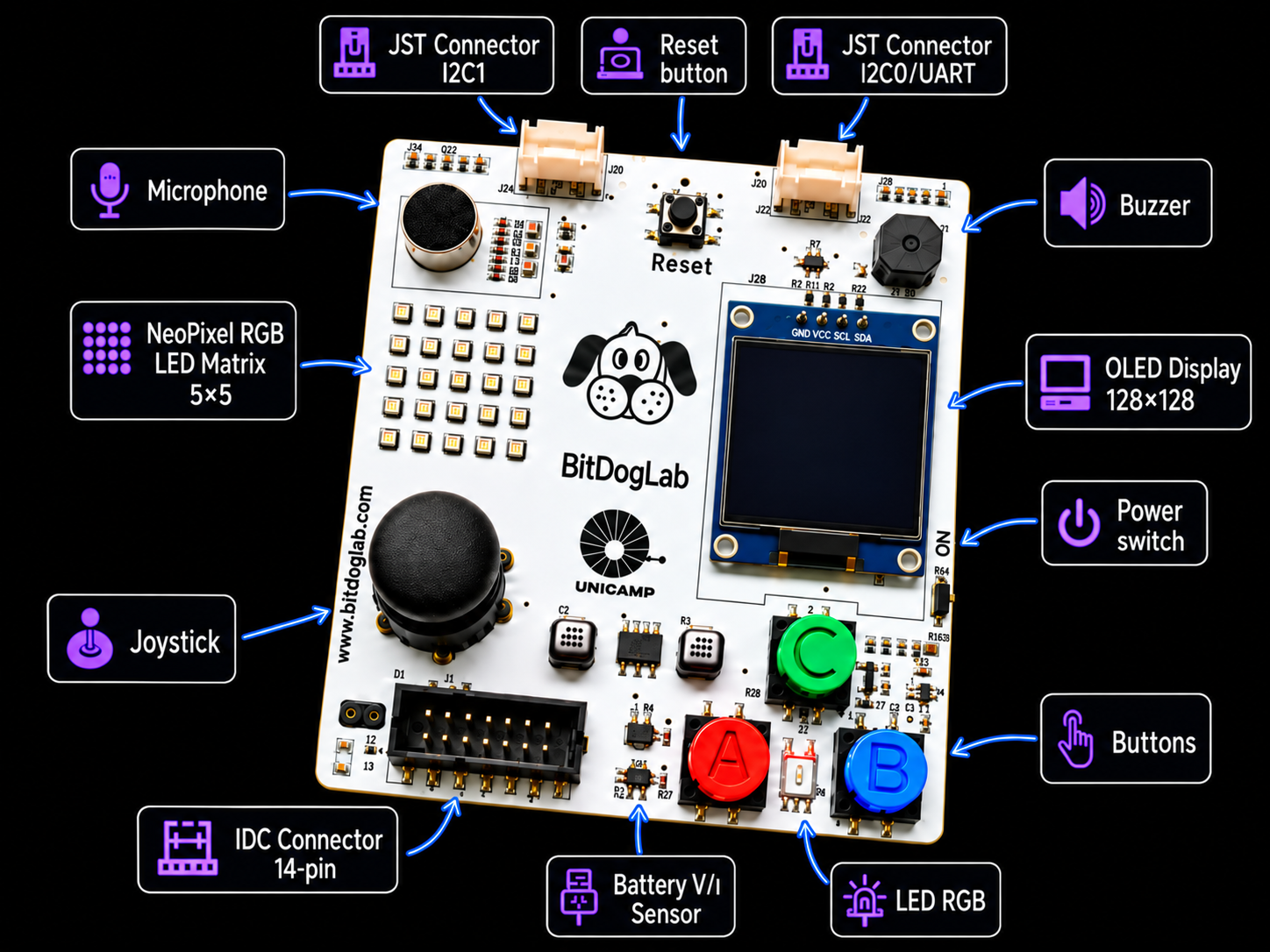
The board provides direct access to the main resources used in embedded-system education, including buttons, joystick, RGB LED, LED matrix, OLED display, microphone, buzzer, sensors, and expansion connectors.
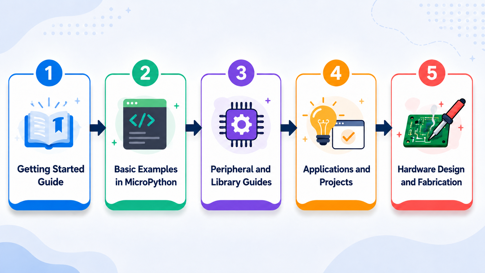
flowchart LR
    A[Start Here guide] --> B[Basic MicroPython examples]
    B --> C[Peripheral guides and libraries]
    C --> D[Applications and projects]
D --> E[Hardware design and fabrication]basic-examples/ directory, organized from simpler to more advanced peripherals.libs_software/ modules.projects/.pcb-prototyping/.The fastest text-based path is MicroPython with Thonny:
Below are the tools currently being developed within the BitDogLab ecosystem to support different entry points into programming — from block-based logic to AI-assisted code generation.
Blockly is the easiest way to get started with BitDogLab. It is designed for students and beginners learning programming logic and embedded systems. The tool runs directly in the browser without requiring installation.
To use it:
Run or Upload to send the program to the BitDogLab.Important: If the board already contains a file named
main.py, remove it before using Blockly. This file can prevent the tool from communicating correctly with the microcontroller.

The BIH is a hardware information database designed to adapt the BitDogLab technical context for Large Language Models (LLMs), including ChatGPT, Gemini, and other AI assistants.
It describes the board's pin assignments, peripherals, interfaces, and hardware constraints. By providing the BIH to an LLM before requesting a program, the model can generate MicroPython or C/C++ code that better matches the BitDogLab hardware.
O BitDogLab FluxCode é um aplicativo Android que usa IA multimodal para transformar fluxogramas desenhados à mão em código MicroPython pronto para rodar na BitDogLab. A proposta é desplugada: o estudante primeiro desenvolve a lógica no papel usando símbolos de fluxograma, fotografa o desenho pelo app e recebe automaticamente o código correspondente, que pode ser executado ou salvo direto na placa.
Para usar:
main.py para execução automática ao ligar.Disponível apenas para Android. Requer MicroPython instalado na placa e um cabo USB compatível com transferência de dados (não apenas carregamento).
UNDER CONSTRUCTION
BitDogLab V7 integrates an RGB LED, a 5x5 WS2812B matrix, three buttons, analog joystick, buzzer, analog microphone, OLED display, power monitoring, and expansion connections around a Raspberry Pi Pico-compatible module.
The V7 hardware was developed in Altium Designer. Source files, schematic, PCB layout, BOM, pick-and-place data, STEP model, and public Gerber files for fabrication are available in pcb-prototyping/BitDogLab V7/.
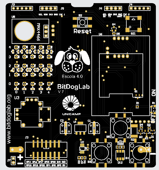
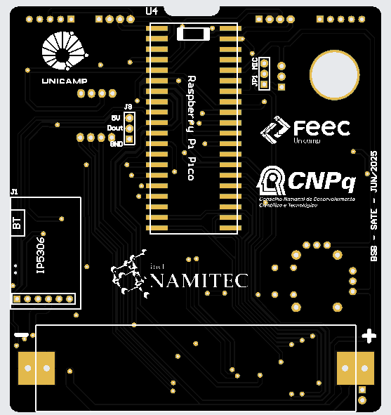
BitDogLab V6 was developed in KiCad and remains available for study and fabrication. See the complete PCB and fabrication documentation.
| Path | Content |
|---|---|
basic-examples/ | Beginner-friendly MicroPython examples organized by peripheral. |
doc/ | BitDogLab V6 and V7 documentation and peripheral guides. |
firmware/ | MicroPython firmware and installation resources. |
libs_software/ | Reusable MicroPython drivers and helper modules. |
pcb-prototyping/ | PCB source files and public manufacturing files. |
projects/ | Applications, sensors, IoT, tools, and hardware expansions. |
BitDogLab is open hardware. Its design and fabrication files are publicly available for study, modification, and manufacturing.
The project is licensed under the CERN Open Hardware Licence Version 2 - Strongly Reciprocal (CERN-OHL-S v2.0). See LICENSE.
| Qty | Value | Footprint | References |
|---|---|---|---|
| 4 | Conn_01x02_Pin | Connector_JST:JST_XH_B2B-XH-A_1x02_P2.50mm_Vertical | J1, J2, J3, J7 |
| 4 | Conn_01x03_Pin | Connector_JST:JST_XH_B3B-XH-A_1x03_P2.50mm_Vertical | J11, J12, J13, J14 |
| 2 | Conn_01x01_Pin | Connector_PinHeader_2.54mm:PinHeader_1x01_P2.54mm_Vertical | J4, J5 |
| 2 | ROB-14450 | ROB-14450:ROB14450 | U2, U3 |
| 1 | 815 | PCA_modulo:MODULE_815 | U1 |
| 1 | C | Capacitor_THT:C_Radial_D6.3mm_H11.0mm_P2.50mm | C2 |
| 1 | Conn_01x04_Pin | Connector_JST:JST_XH_B4B-XH-A_1x04_P2.50mm_Vertical | J15 |
| 1 | MC78M06BTG | MC78M06:TO220-3_ONS | U5 |
| 1 | XT30-M | XT30:AMASS_XT30PW-M | J6 |
BitDogLab/BitDogLab
Open-source educational hardware for embedded systems, programming, electronics, and physical computing.

BitDogLab/BitDogLab
Open-source educational hardware for embedded systems, programming, electronics, and physical computing.

BitDogLab/BitDogLab
Open-source educational hardware for embedded systems, programming, electronics, and physical computing.

GonzaCerv/noah-hardware
This repo contains all the hardware description for the Noah project. Here lies 3D models, electronics PCB and Firmware software of the robot.

bonavirak/Line-Follower-Robot-Using-STM32F103C8T6-with-TCRT-5000
Line Follower Robot powered by STM32F103C8T6 microcontroller, using TCRT5000 5-way sensors for line detection, HC-05 for Bluetooth communication, TB6612FNG motor driver, and N20 motors (1000 RPM).

0x23/BallJointEmbossingMachine
A motorized linear embossing machine designed to precisely press ball joints. It was designed to automate the production of balljoint linkages for the Open-Micro-Manipulator.


team-mountaineers-urc-2023/electronics
Block diagrams, schematics, and PCB files related to the electronics subteam


It measures 70 × 70 mm and has 2 copper layers, 1.6 mm thick.
17 parts, built around the ROB-14450. The full list of its parts is on this page, with links to each part's symbol and footprint where PCBKit's library has them.
From the BitDogLab/BitDogLab repository on GitHub, at the commit this page was made from: the board is projects/hardware-expansion/RoboMovel/placa_kicad/Projeto_PCA9685.kicad_pcb and its schematic pcb-prototyping/BitDogLab V6/bitdoglab-smd/bitdoglab_main/bitdoglab_smd.kicad_sch. PCBKit opens the board in the browser, with nothing to install.
Its repository states no licence, so its author keeps all rights: ask BitDogLab before reusing the design.