2 layers95.8 × 96.6 mm
Panelized
unicab369/ESP-MESS
I am building a Wireless Bridge System that can manage multiple devices using a variety of wireless technologies.
324 parts

 bitbank2/LED_Clock6
A low cost PCB project (w/firmware) for a dark-room-friendly digital clock
LED Clock is an open-source printed circuit board by bitbank2, from the bitbank2/LED_Clock repository on GitHub, published under the Apache-2.0 licence. It is a 2-layer board of 134 × 38.5 mm with 97 parts on 51 nets, routed with 581 tracks and 48 vias.
It is built around the APDS-9960, AO3400A and DS3231MZ+. Its parts include 58 diodes, 17 resistors, 5 capacitors, 4 transistors and 1 connector. It belongs with the lEDs and displays boards and the RISC-V boards of this library.


A CH32V003 low cost 'night clock'
The PCB project was created with KiCad 7.0 and the firmware in the MounRiver Studio IDE. The target device is the TSSOP20 version of the CH32V003.
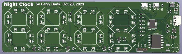
Why did you make it?
We like to sleep in a completely black room with no LEDs visible. In the winter, the sun comes up later in the morning and it's useful to know what time it is if you wake up too early and can try to sleep a bit more. My idea was to create an LED clock which displays the time in the day and goes completely black at night. To display the time in a dark room, you wave your hand close to the clock and it will dimly display the time for a few seconds.
The KiCad project files and gerbers (ready to produce at your favorite PCB fab) are in the PCB folder.
If you find this project useful, please consider becoming a sponsor or sending a donation.

| Qty | Value | Footprint | References |
|---|---|---|---|
| 58 | LED | LED_SMD:LED_0603_1608Metric | D1, D2, D10, D11, D12, D13, D14, D15, D16, D17, D18, D19, D20, D21, D22, D23 +42 |
| 8 | 1K | Resistor_SMD:R_0603_1608Metric | R1, R2, R3, R4, R5, R6, R7, R17 |
| 4 | 1k | Resistor_SMD:R_0603_1608Metric | R10, R14, R15, R16 |
| 4 | AO3400A | Package_TO_SOT_SMD:SOT-23 | Q1, Q2, Q3, Q4 |
| 4 | LOGO | LOGO | G***, G***, G***, G*** |
| 2 | 10K | Resistor_SMD:R_0603_1608Metric | R11, R12 |
| 2 | 10uF | Capacitor_SMD:C_0603_1608Metric | C1, C5 |
| 2 | 1uF | Capacitor_SMD:C_0603_1608Metric | C3, C4 |
| 2 | 4.7K | Resistor_SMD:R_0603_1608Metric | R8, R9 |
| 2 | SW_Push | Button_Switch_SMD:SW_Push_1P1T_NO_Vertical_Wuerth_434133025816 | PUSH1, PUSH2 |
| 1 | 100n | Capacitor_SMD:C_0603_1608Metric | C2 |
| 1 | 22R | Resistor_SMD:R_0603_1608Metric | R13 |
| 1 | AP2127K-3.3 | Package_TO_SOT_SMD:SOT-23-5 | LDO |
| 1 | APDS-9960 | Sensor:Avago_APDS-9960 | APDS-9930 |
| 1 | Battery_Cell | Battery:CR44_Tabs | 3V Batt |
| 1 | CH32V003_TSSOP20 | Package_SO:TSSOP-20_4.4x6.5mm_P0.65mm | CH32V003 |
| 1 | DS3231M | Package_SO:SOIC-16W_7.5x10.3mm_P1.27mm | DS3231 |
| 1 | PROG | Connector_PinHeader_2.54mm:PinHeader_1x03_P2.54mm_Vertical | J3 |
| 1 | USB_B_Micro | Connector_USB:USB_Micro-B_Molex_47346-0001 | USB |
It measures 134 × 38.5 mm and has 2 copper layers, 1.6 mm thick.
97 parts, built around the APDS-9960, AO3400A and DS3231MZ+. The full list of its parts is on this page, with links to each part's symbol and footprint where PCBKit's library has them.
From the bitbank2/LED_Clock repository on GitHub, at the commit this page was made from: the board is PCB/LED_Clock.kicad_pcb and its schematic PCB/LED_Clock.kicad_sch. PCBKit opens the board in the browser, with nothing to install.
Its repository publishes it under the Apache-2.0 licence: you may reuse it on that licence's terms (keep the author's notice, and for a copyleft licence share your changes alike).
unicab369/ESP-MESS
I am building a Wireless Bridge System that can manage multiple devices using a variety of wireless technologies.


MAATHES-THILAK-K/4CH_RELAY_TIMER
ESP32C3 Mini Based 4CH Relay With Timer Control


lalithk06/Esp32_Smart_Plug
Hardware reference design for an ESP32-S3 smart plug with mains power conversion, relay switching, RTC support, USB connectivity, and protection components.

MAATHES-THILAK-K/Solder-Master-PRO
Professional-grade soldering temperature control on a DIY budget

miekush/fluke-87v-alarm-clock
ATMEGA328P based Alarm Clock PCB for the Fluke 87V

MohamadAminGhanoum/Smart-room-V2
I have since around 1 year done a smart room, where i made a custom pcb, and salvaged some parts from an old laptop motherboard to be able to control the LED strip that i have and also open and close my curtain, but…