2 layers105 × 58 mm
ViRa V1.0
VikramR3/ViRa_Ai_plug
ESP32-S3 mains smart plug: HLK-5M05 isolated supply, SRD-05VDC relay, DS3231M RTC. 2-layer KiCad design.
80 partsMIT

 lalithk06/Esp32_Smart_Plug
Hardware reference design for an ESP32-S3 smart plug with mains power conversion, relay switching, RTC support, USB connectivity, and protection components. Built to explore real-world embedded hardware and power electronics design. The design is recreated for educational purposes to understand mains-powered embedded hardware.
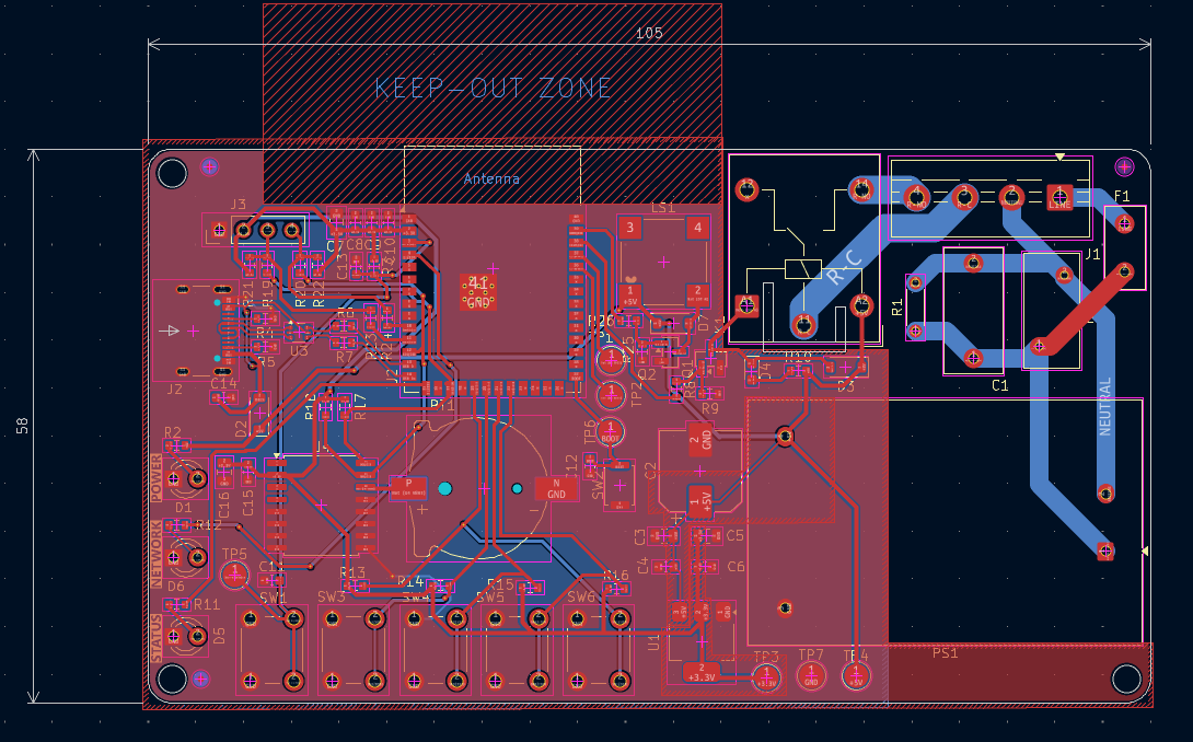
ZAP-010A is an open-source printed circuit board by lalithk06, from the lalithk06/Esp32_Smart_Plug repository on GitHub. It is a 2-layer board of 105 × 58 mm with 80 parts on 69 nets, routed with 400 tracks and 24 vias.
It is built around the ESP32-S3-WROOM-1-N8, HLK-5M05 and AMS1117-3.3, with the DS3231MZ+, USBLC6-2P6 and 1N4148W among its other parts. Its parts include 26 resistors, 16 capacitors, 7 diodes, 7 switches and 4 ICs. It belongs with the home automation and IoT boards and the ESP32 boards of this library.


A compact and efficient smart plug built around the ESP32-S3 for intelligent power control, protection, and connectivity.
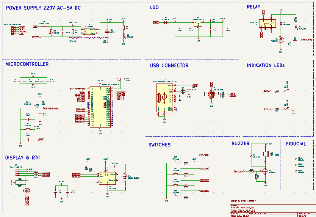
This project presents the schematic and PCB design of a smart plug capable of switching AC loads while supporting modern embedded features such as USB connectivity, RTC support, and protection circuitry. Designed to explore real-world embedded hardware development and PCB design practices.
📺 This project was developed by following a YouTube playlist by Ampnics, with additional learning and implementation.
To design and develop a reliable hardware platform for a smart plug that demonstrates safe mains power handling, embedded control, and scalable architecture for future IoT-based automation.
| No. | Components | Specifications / Role |
|---|---|---|
| 1. | ESP32-S3 Module | Main microcontroller with Wi-Fi & BLE |
| 2. | Relay | AC load switching |
| 3. | AC-DC Power Module | Converts mains to regulated DC |
| 4. | Voltage Regulators | Stable voltage supply |
| 5. | Protection Circuitry | Fuse, MOV, flyback diode, etc. |
| 6. | USB Interface | Programming & debugging |
| 7. | Capacitors & Resistors | Filtering and biasing |
| 8. | RTC (Optional) | Time-based control support |
| Parameter | Value |
|---|---|
| Input Voltage | 230V AC |
| Output Control | Relay-based switching |
| MCU | ESP32-S3 |
| Communication | Wi-Fi, BLE |
✅ Designed with real-world electrical safety considerations
✅ Suitable for home automation applications
✅ Expandable for IoT integration
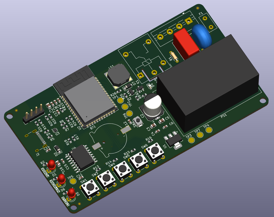
✅ Compact PCB layout
✅ Industry-relevant hardware design workflow
⭐ This project is part of my learning journey in hardware design and PCB development.
| Qty | Value | Footprint | References |
|---|---|---|---|
| 10 | 0.1uF | Capacitor_SMD:C_0603_1608Metric | C4, C6, C8, C9, C10, C11, C12, C13, C14, C15 |
| 10 | 10K | Resistor_SMD:R_0603_1608Metric | R9, R13, R14, R15, R16, R17, R18, R21, R22, R25 |
| 6 | 0R | Resistor_SMD:R_0603_1608Metric | R6, R7, R19, R20, R23, R24 |
| 5 | 1K | Resistor_SMD:R_0603_1608Metric | R8, R10, R11, R12, R26 |
| 5 | SW_Push | Button_Switch_THT:SW_PUSH_6mm | SW1, SW3, SW4, SW5, SW6 |
| 3 | 10uF | Capacitor_SMD:C_0805_2012Metric | C3, C5, C7 |
| 3 | Fiducial | Fiducial:Fiducial_0.75mm_Mask1.5mm | FID1, FID2, FID3 |
| 3 | RED_LED | LED_THT:LED_D3.0mm | D1, D5, D6 |
| 2 | 1N4148W | Diode_SMD:D_SOD-123 | D3, D7 |
| 2 | 5k | Resistor_SMD:R_0603_1608Metric | R4, R5 |
| 2 | AO3400A | Package_TO_SOT_SMD:SOT-23 | Q1, Q2 |
| 1 | 0.1uF | Capacitor_THT:C_Rect_L13.0mm_W6.0mm_P10.00mm_FKS3_FKP3_MKS4 | C1 |
| 1 | 10D56K | Varistor:RV_Disc_D12mm_W5.8mm_P7.5mm | RV1 |
| 1 | 10k | Resistor_SMD:R_0603_1608Metric | R3 |
| 1 | 1M | Resistor_THT:R_Axial_DIN0204_L3.6mm_D1.6mm_P5.08mm_Horizontal | R1 |
| 1 | 2.2uF | Capacitor_SMD:C_0805_2012Metric | C16 |
| 1 | 220uF | Capacitor_SMD:CP_Elec_8x10 | C2 |
| 1 | 3V3 | Test Point:TestPoint_Pad_D2.5mm | TP3 |
| 1 | 4k | Resistor_SMD:R_0603_1608Metric | R2 |
| 1 | 500mA 250V | Fuse:Fuse_Littelfuse_395Series | F1 |
| 1 | 5V | Test Point:TestPoint_Pad_D2.5mm | TP4 |
| 1 | AMS1117-3.3 | Package_TO_SOT_SMD:SOT-223-3_TabPin2 | U1 |
| 1 | BOOT | Test Point:TestPoint_Pad_D2.5mm | TP6 |
| 1 | CH291-1220LF | CH291-1220LF:BAT_CH291-1220LF | BT1 |
| 1 | Conn_01x04_Pin | Connector_PinHeader_2.54mm:PinHeader_1x04_P2.54mm_Vertical | J3 |
| 1 | DS3231M | Package_SO:SOIC-16W_7.5x10.3mm_P1.27mm | U4 |
| 1 | EN | Test Point:TestPoint_Pad_D2.5mm | TP5 |
| 1 | ESP32-S3-WROOM-1 | RF_Module:ESP32-S3-WROOM-1 | U2 |
| 1 | GND | Test Point:TestPoint_Pad_D2.5mm | TP7 |
| 1 | HLK-5M05 | Converter_ACDC:Converter_ACDC_Hi-Link_HLK-5Mxx | PS1 |
| 1 | MBR0520 | Diode_SMD:D_SOD-123 | D2 |
| 1 | MLT-8530 | footprints:MLT-8530_JHE | LS1 |
| 1 | RED_LED | LED_SMD:LED_0603_1608Metric_Pad1.05x0.95mm_HandSolder | D4 |
| 1 | RXD0 | Test Point:TestPoint_Pad_D2.5mm | TP2 |
| 1 | Relay_SPDT | Relay_THT:Relay_SPDT_Hongfa_HF3F-L-xx-1ZL1T | K1 |
| 1 | SW_Push | Button_Switch_SMD:SW_Push_SPST_NO_Alps_SKRK | SW2 |
| 1 | Screw_Terminal_01x04 | TerminalBlock:TerminalBlock_MaiXu_MX126-5.0-04P_1x04_P5.00mm | J1 |
| 1 | TXD0 | Test Point:TestPoint_Pad_D2.5mm | TP1 |
| 1 | USBLC6-2P6 | Package_TO_SOT_SMD:SOT-666 | U3 |
| 1 | USB_C_Receptacle_USB2.0_16P | Connector_USB:USB_C_Receptacle_HCTL_HC-TYPE-C-16P-01A | J2 |
VikramR3/ViRa_Ai_plug
ESP32-S3 mains smart plug: HLK-5M05 isolated supply, SRD-05VDC relay, DS3231M RTC. 2-layer KiCad design.

ponrajleo/AI-Hardware-ESP32S3-
This project is part of a complete open-source hardware design course on YouTube:

lalithk06/PCB_Designs
This repository contains various PCB design projects made using KiCad

ajkumar-1907/POWER-ELECTRONICS-LIB
Open-source library of power electronics converter topologies — KiCad schematics, working principles, use cases, and design notes for DC-DC, AC-DC, DC-AC, and AC-AC converters. Free to use, modify, and build on.

Jankyneering/Waffle_hw
Hardware designs for Waffle, a compact Pager and general RF multitool.

tsmiltonAgents/pl60c-dmx-wakeup
A small ESP32-S3 board that drives the wired DMX512 input of a Neewer PL60C panel light so the light can be ramped up slowly in the morning (sunrise alarm). Rev A, 2026-09-02.


It measures 105 × 58 mm and has 2 copper layers, 1.6 mm thick.
80 parts, built around the ESP32-S3-WROOM-1-N8, HLK-5M05, AMS1117-3.3 and DS3231MZ+. The full list of its parts is on this page, with links to each part's symbol and footprint where PCBKit's library has them.
From the lalithk06/Esp32_Smart_Plug repository on GitHub, at the commit this page was made from: the board is Hardware/Hardware Design/ZAP-010A.kicad_pcb and its schematic Hardware/Hardware Design/ZAP-010A.kicad_sch. PCBKit opens the board in the browser, with nothing to install.
Its repository states no licence, so its author keeps all rights: ask lalithk06 before reusing the design.