The CANT project is designed to allow people to screw around with CAN easily at layers 1/2. All of the stuff that is normally handled by a CAN controller that is baked into sillicon is up for grabs.
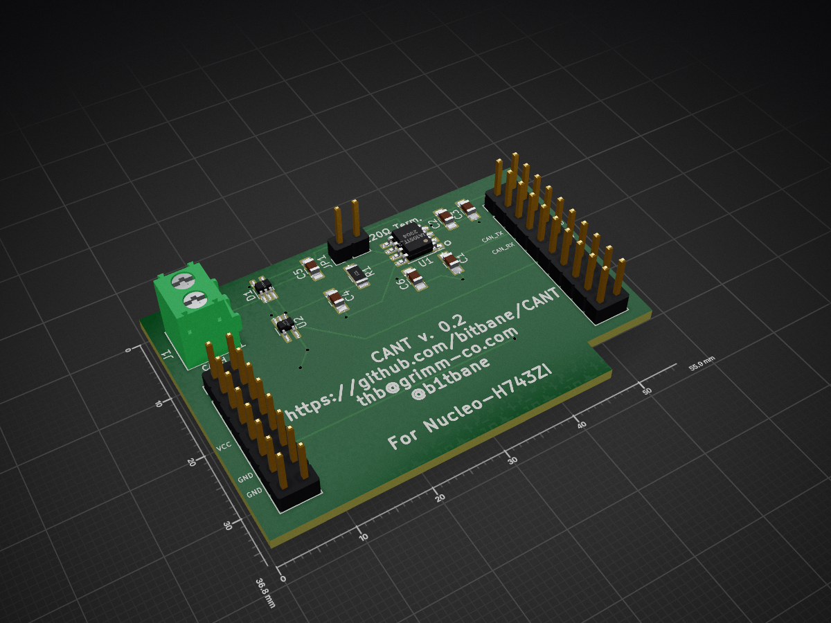
CANT is an open-source printed circuit board by bitbane, from the bitbane/CANT repository on GitHub, published under the BSD-3-Clause licence. It is a 2-layer board of 55.9 × 36.8 mm with 15 parts on 38 nets, routed with 134 tracks and 11 vias.
It is built around the TJA1051T/3/1, 74LVC1G66GW and SP1002-02JTG. Its parts include 6 capacitors, 3 connectors, 2 ICs, 1 resistor and 1 diode.
The CANT project is designed to allow people to screw around with CAN easily at layers 1/2.
All of the stuff that is normally handled by a CAN controller that is baked into sillicon is up for grabs.
CANT is designed to run on an ST Micro Nucleo-H743ZI
(Update: The Nucleo-H743ZI has been discontinued. Its replacement the Nucleo-H743ZI2 works with CANT out of the box).
development board. This board was chosen due to its speed (400MHz) and essentially infinite ram and flash.
Note: If you have a MB1364C (and possibly D) revision of this board, the solder bridge at SB7 has to be soldered
closed to enable the GPIO pin. On revisions B and E this is controlled by the jumper JP6 which is in place by default.
Getting started with the Nucleo-STM32H7 development board
The Nucleo-H743ZI board has an STLink V2.1 debugger built in, available via the Micro-USB port on the
opposite side of the board from the RJ-45 jack. This port provides the serial port for communication,
as well as the debugging interface. The serial port has a baud rate of 115200 kbps, 8N1.
For CAN communication, PB12 is CAN RX and PB13 is CAN TX. Conveniently the CAN2 peripheral can also be
multiplexed to these pins, so switching from normal CAN operation to CANT operation would be
possible without rewiring. This is currently not implemented. I'm using the
TI SN65HVD232 3.3V CAN transceiver,
but any 3.3V CAN Transceiver should work. Some transceivers may require some additional
programming or wiring, so check that if you go with something else.
If you are using the CANT shield, pin PA5 is used to toggle the analog switch that shorts CANH and CANL
together.
Additionally, GPIO pins PA4 and PA15 are configured as GPIO outputs. I find banging on these
useful during debugging. These pins, along with the two pins for the CAN peripheral, are all located
on connector CN7, on the upper-right of the dev board if the RJ-45 connector is pointed towards you.
STs documentation contains the schematics for this board, but connector CN7 is reproduced here for
convenience:
PIN
PIN
PC6
1
2
PB8
PB15
3
4
PB9
PB13
5
6
AVDD
PB12
7
8
GND
PA15
9
10
PA5
PC7
11
12
PA6
PB5
13
14
PB3
15
16
PD14
PA4
17
18
PD15
PB4
19
20
PF12
Flashing pre-built CANT
The Nucleo-H743ZI dev board will present itself as a USB mass storage device. Dragging and dropping the CANT.bin file
located in the firmware/ folder to the dev board should properly flash the code to the dev board.
Alternatively, you will need openocd installed to flash the prebuilt CANT. At the time of this writing the latest version
of openocd (0.10.0) does not support the H743ZI, but it is supported in the openocd git repository.
Presumably support will be added in the next release of openocd. In order to flash the prebuilt CANT, type
text
make flash_prebuilt
LEDs
The green LED (LED1) flashes at a rate of 1hz. The blue LED (LED2) changes state for every 128 CAN frames
that CANT has received. This is handy for ensuring that the CAN bus isn't dead and that CANT is properly
configured.
Demos
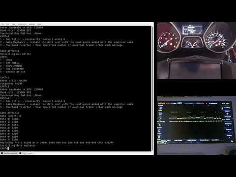
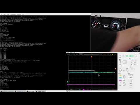
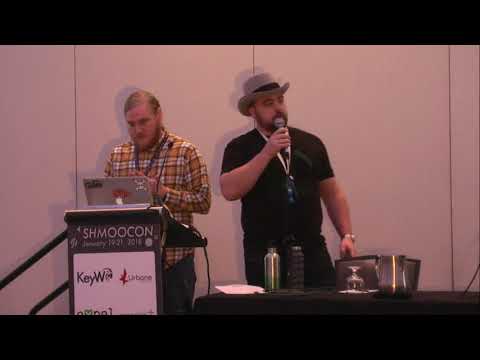
Demo videos from my talks
Original Shmoocon Talk:
Defcon 26 CHV Talk:
Developing with CANT
NOTE: Some older versions of the arm-none-eabi-gcc toolchain generate invalid opcodes with the optimizations that CANT uses. Specifically, the 4.9.3 version that ships with Ubuntu 16.04 tries to generate ARM instructions and switch to ARM mode, which the Cortex-M7 part does not support. If CANT just isn't working and you are winding up in the hardfault handler, this is likely the issue. Upgrade to a newer compiler version to fix this issue. The 7 series and newer seem to all work fine.
To start developing on CANT, all you need is an arm-none-eabi toolcahin installed and in your path.
Shield
Version 0.1 of the shield was designed with a TI SN65HVD232DRG4 CAN transceiver, which costs about $1.75. Version 0.2 was redesigned for a TJA1051T/3 CAN transceiver which costs a little under a dollar. Version 0.2 also has an additional capacitor C6 for filtering the VIO line on the TJA1051T/3. Besides those changes, v0.1 and v0.2 are identical. Cost for building one is about $3.40 for one, or about $22.75 for 10, plus the cost of the PCB.
It measures 55.9 × 36.8 mm and has 2 copper layers, 1.6 mm thick.
What parts does the CANT use?
15 parts, built around the TJA1051T/3/1, 74LVC1G66GW and SP1002-02JTG. The full list of its parts is on this page, with links to each part's symbol and footprint where PCBKit's library has them.
Where can I download the CANT KiCad files?
From the bitbane/CANT repository on GitHub, at the commit this page was made from: the board is CANT_Shield/CANT.kicad_pcb. PCBKit opens the board in the browser, with nothing to install.
Can I use the CANT design in my own project?
Its repository publishes it under the BSD-3-Clause licence: you may reuse it on that licence's terms (keep the author's notice, and for a copyleft licence share your changes alike).
Nui is an IR(evntually also BLE) controlled volume controller for analog audio. It sits between your audio source and speakers and can amplify or reduce the volume using IR commands (and evntually BLE).
Converts a standard I2C signal into a Differential I2C signal. This improves signal integrity over long distances while using the same hardware as I2C.