Universal 16-channel analog marine gateway for boats with legacy VDO sensors. Connects analog instruments to MQTT and Signal K without sensor replacement. ESP32-based, open source, modular mini-board system.
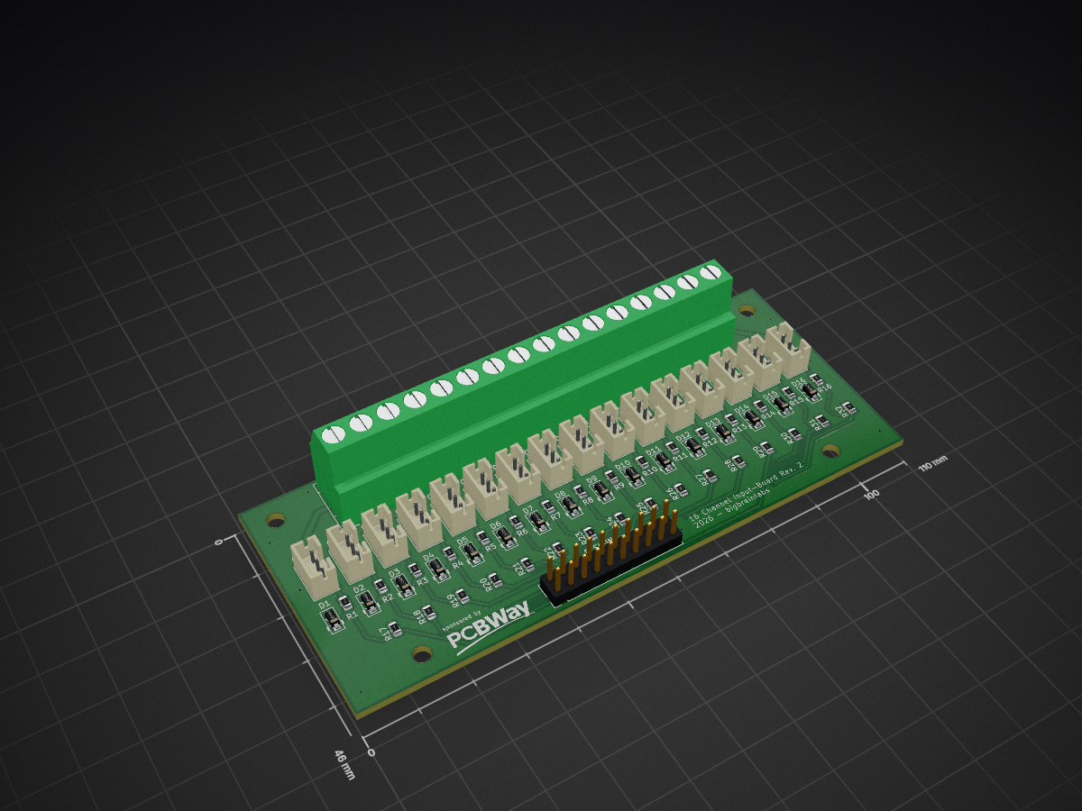
Input board is an open-source printed circuit board by bigbrainlabs, from the bigbrainlabs/BoatOpenIO repository on GitHub. It is a 2-layer board of 110 × 46 mm with 70 parts on 52 nets, routed with 254 tracks and 15 vias.
Its parts include 32 resistors, 16 diodes and 1 connector. It belongs with the sensors and measurement and home automation and IoT boards and the ESP32 boards of this library.
README
README.md
BoatOpenIO
Universal Marine IO System – Open Source, modular, fully configurable
"Plug in, configure, done."
BoatOpenIO is an open hardware platform for sensor integration on boats. Each of the 16 sensor terminals can be freely assigned to any of the up to 16 input channels via software. Pluggable mini-boards handle signal conditioning — no soldering, no rewiring.
This project is 100% open source and free. The complete story – every idea, mistake, detour and solution – is documented in the book series "Logbook Without Posing".
If you find this project useful and want to support it: buying the books is the best way.
"Found this useful? Grab a book — or the whole series. You'll be supporting further development."
Note: The ready-made board set is no longer sold on Tindie. Due to the new EU regulation on shipping abroad, the effort is no longer proportionate for me as a private individual. The Gerber files in this repo remain free to download.
The boards can be purchased directly from PCBWay — I've set them up there as projects, so there's nothing to upload yourself: 👉 BoatOpenIO projects on PCBWay
🏭 Boards sponsored by PCBWay
PCBWay sponsors the board manufacturing for BoatOpenIO, the sensor gateway of this ecosystem — thank you!
Always verify which mini-board is plugged into which channel before applying power.
Connecting 12V directly to a pull-up channel (instead of through a voltage divider) will destroy the MUX, all ADS1115 and the ESP32 through I2C chain reaction.
The input board includes protection circuitry (3.3V) on all 16 signal inputs — but correct mini-board assignment is still essential.
Concept
Commercial marine IO systems cost hundreds of euros and are closed black boxes.
BoatOpenIO costs a fraction of that — and anyone can adapt, extend, and improve it.
If your boat was built before 2000, this project was built for you.
Boats from that era came with analog VDO sensors — oil pressure, oil temperature, coolant temperature, tank level, RPM. These sensors are robust, time-tested, and still doing their job perfectly. The problem: no modern system speaks their language.
NMEA 2000 gateways that bridge analog signals to modern boat networks exist — but they cost 300–500€, are closed proprietary boxes, and give you zero insight or control over what happens inside.
BoatOpenIO is an open analog marine gateway.
Plug in your existing VDO sensors. Get clean MQTT output. Forward to Signal K or BoatOS. Done — without replacing a single sensor, without rewiring, without a black box.
text
VDO sensor → BoatOpenIO → MQTT → Signal K / BoatOS → modern dashboard
Built for boats built before 2000 that will sail for another 20 years — and deserve a modern dashboard without a full refit.
Hardware – v2 PCB
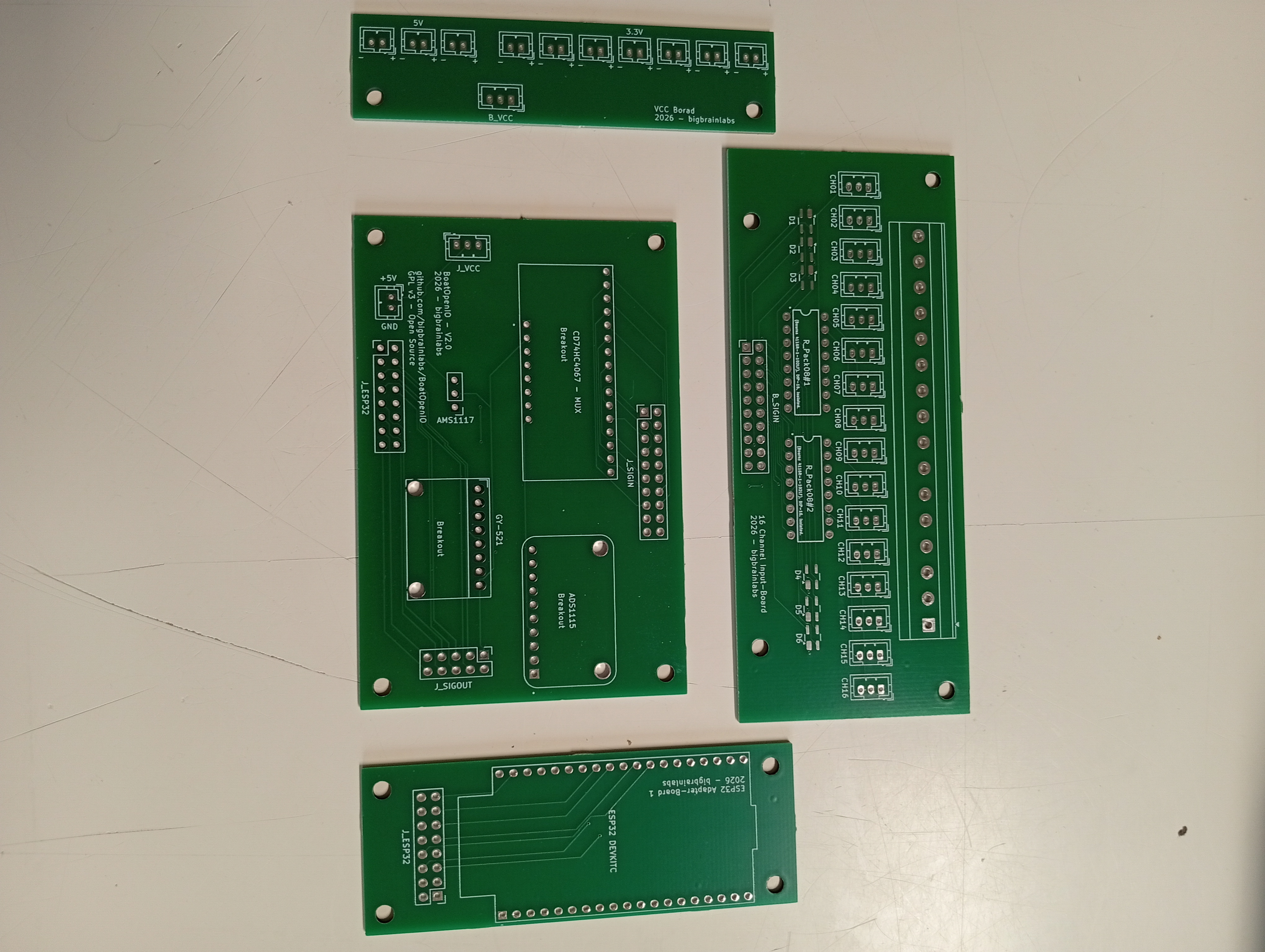
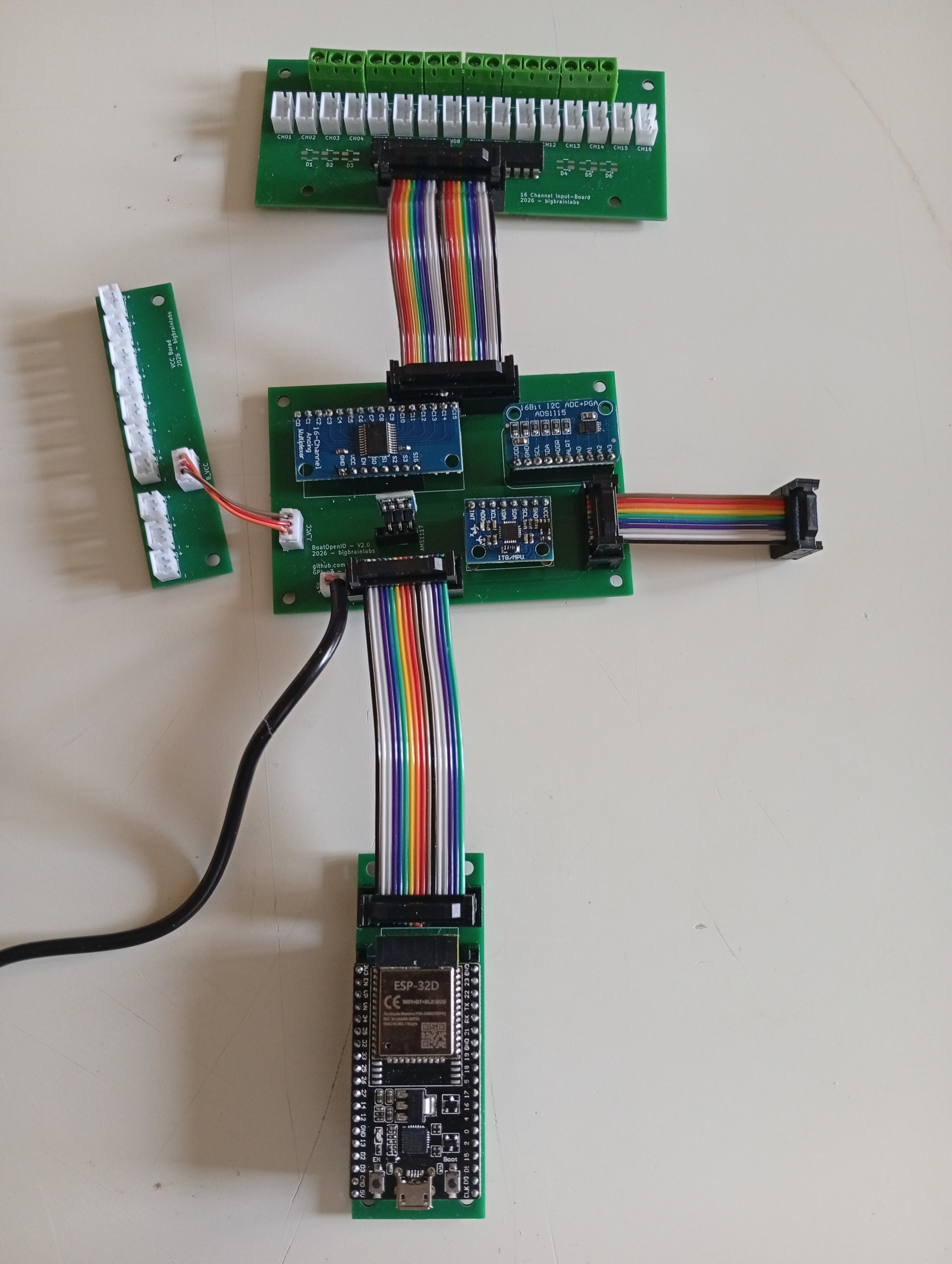
Four separate boards, connected via IDC ribbon cables: input board, main board, ESP32 adapter board, and VCC distributor. Gerber files ready to order in hardware/v2/*/gerber/.
🛒 Ordering the boards: All four boards are set up as projects on PCBWay and can be purchased there directly: PCBWay project page — or upload the Gerbers to a PCB fab of your choice. Bare PCBs, components per the parts list below.
Microcontroller, WiFi, I2C, MUX control – on its own adapter board
✅
CD74HC4067 Breakout
16:1 analog multiplexer
✅
ADS1115 Breakout (1×)
16-bit ADC
✅
MPU6050 Breakout (GY-521)
6-DOF IMU, tilt/impact detection
✅
AMS1117-3.3 Breakout
5V → 3.3V regulator
✅
Everything socketed — no component soldered directly. Faulty ESP32? Swap the adapter board. Done.
The ESP32 sits on its own dedicated adapter board. The first adapter board is designed for the 38-pin ESP32 DevKitC-32D — swappable and ready for future ESP32 variants.
Protection Circuit (Input Board)
Every one of the 16 signal inputs has a hardware protection circuit, directly on the input board:
⚠️ Pull-up voltage is 3.3V — the ADS1115 VDD is at 3.3V; higher voltages on the inputs risk component damage.
Running without the protection circuit (not recommended)
If the Bourns or Zener components are unavailable and you want to get the board running first, the resistor networks can be bypassed — but understand what you are giving up.
How to bypass the Bourns 4116R-1-102LF:
The DIL-16 package contains 8 isolated resistors. Each resistor connects a pin on the left row to the opposing pin on the right row:
To bypass: solder a short jumper wire across each pair (8 bridges per chip, 16 total for both R_Pack08). The signal then passes through without series resistance. The SP0503BAHTG Zener pads can simply be left empty.
🔴 Without this protection, all 16 inputs are exposed. A wrong mini-board, a wiring mistake, or any brief overvoltage can destroy the MUX, ADS1115, and ESP32 in a chain reaction — all three at once. Only bypass for bench tests with known, clean signals. Fit the real parts before installing on the boat.
Input Board – Connectors
text
16× screw terminal 5.08mm   → raw sensor signal
20-pin IDC header            → connection to main board (SIG1–16 + GND)
VCC Board – Connectors
The VCC board distributes power to the mini-boards via JST connectors. It connects to the main board via a 3-pin JST cable (5V, 3.3V, GND).
text
7× JST 2-pin (3.3V)         → VCC rail for passive/ESP01 mini-boards
3× JST 2-pin (5V)           → VCC rail for Arduino Nano mini-boards
3-pin JST                   → connection to main board (5V · 3.3V · GND)
I2C Address
Only 1× ADS1115 fitted (the MUX routes all 16 channels onto a single signal line) → fixed address 0x48.
GPIO Assignment (ESP32, via 16-pin main board ↔ adapter board connector)
GPIO
Function
GPIO21
I2C SDA
GPIO22
I2C SCL
GPIO14
MUX S0
GPIO27
MUX S1
GPIO26
MUX S2
GPIO25
MUX S3
GPIO4 / 5 / 13 / 16 / 17 / 18 / 19 / 23
OUT1–OUT8 (prepared for output channels)
Output Channels (prepared)
The main board already has a 10-pin header prepared for 8 signal output channels (+5V/GND) — e.g. for heaters, pumps, horns via relay or MOSFET mini-boards. Works on the same plug-in principle as the inputs.
Compatible ESP32 Modules (first adapter board)
The footprint fits all modules in the 38-pin DevKitC layout: ESP32-WROOM-32 / -32D / -32E / -32U / -32UE, as well as ESP32-SOLO-1.
⚠️ ESP32-WROVER is NOT compatible — GPIO16/17 are internally reserved for PSRAM on WROVER and therefore blocked for output channels.
Mini-Boards (pluggable)
Type
Code
Use case
Voltage divider
VT
12V VDO sensors → 3.3V
Pull-down
PD
Digital sensors, switches
Pull-up
PU
Open-collector outputs
Schmitt trigger
ST
Magnetic pickup sensors, 50Hz generators
Pulse board
ISP
RPM, flow (Arduino Nano / ESP01)
Optocoupler
OPT
Galvanic isolation (W-terminal RPM)
Direct / jumper
DIR
3.3V signals directly
GND collector
GND
Multiple sensor ground loops → single reference
MotorCombo — everything on one board
The MotorCombo taps the most common engine sensors directly, so you don't have to plug in six separate mini-boards:
Channel
Conditioning
Battery 1 + 2
Voltage divider
Oil pressure
Pull-up
Temperature
Pull-up
Tank
Pull-up
RPM
Optocoupler + ESP-01
MotorCombo THT — through-hole, hand-solderable. Gerbers and documentation are in the repo. Resistor values are deliberately left open so everyone can fit what matches their own VDO senders — which is also why there is no pre-assembled SMD variant: with the values depending on the senders, a fixed pre-populated board makes no sense.
Design and submit your own mini-boards — pull requests welcome!
Multiplexer Logic
The CD74HC4067 routes one of 16 inputs onto the shared ADS pin A0 via a 4-bit address (S3–S0). Address and chip input follow the datasheet: 0000 → C0 … 1111 → C15.
Rev.1 note — channels are mirrored in software. On the Rev.1 board the channel wiring is reversed (terminal 1 sits on the input that address 1111 selects, terminal 16 on 0000). The firmware compensates in software (MUX_MIRROR): terminal N → address 16 − N. The terminal numbering you see is therefore correct. A later board revision straightens the wiring, then the mirror is switched off (MUX_MIRROR 0).
All 16 channels are routed via the MUX (CD74HC4067) to a single ADS1115 @ 0x48 on pin A0. No ads or pin fields needed — the channel number (klemme) maps directly to the MUX select lines.
topic — optional. If empty (""), the firmware publishes to boat/io/<sensor> (default). Set a custom topic for Signal K compatibility or any other MQTT schema. The "SK" button in the web UI auto-fills the correct Signal K path for common sensor names.
Channel topics are set per channel (topic field / web UI). Pitch, roll and the impact base topic are editable under WiFi & MQTT in the web UI (defaults boat/io/pitch, boat/io/roll, boat/alarm/impact; the impact base gets _g / _severity / _active appended). In test mode the impact alarms are redirected to boat/test/alarm/impact_* so demo impacts never trigger real dashboards.
Amazon: faster delivery. AliExpress links to follow.
Item 10 comes from Conrad, not Amazon: the same Bourns part is around €1.30 there versus roughly €10. For the 2 pieces needed that saves nearly €18. The Amazon link beside it is just the fallback source.
Item 20 is the bare boards only. Items 1–19 are the components you still need.
Free to use, modify, distribute — derivative works must also be GPL-3.0. See LICENSE.
Exception: the community enclosure designs in hardware/enclosures/ are licensed CC BY-SA 4.0 — the better fit for CAD work. Submitting a design means licensing it that way; see the enclosure README.
Part of the Series
Logbook Without Posing — authentic DIY projects around boating.
"Build it yourself and you know what's in it — and what it cost."
Universal 16-channel analog marine gateway for boats with legacy VDO sensors. Connects analog instruments to MQTT and Signal K without sensor replacement. ESP32-based, open source, modular mini-board system.
Universal 16-channel analog marine gateway for boats with legacy VDO sensors. Connects analog instruments to MQTT and Signal K without sensor replacement. ESP32-based, open source, modular mini-board system.
Universal 16-channel analog marine gateway for boats with legacy VDO sensors. Connects analog instruments to MQTT and Signal K without sensor replacement. ESP32-based, open source, modular mini-board system.
Universal 16-channel analog marine gateway for boats with legacy VDO sensors. Connects analog instruments to MQTT and Signal K without sensor replacement. ESP32-based, open source, modular mini-board system.
Universal 16-channel analog marine gateway for boats with legacy VDO sensors. Connects analog instruments to MQTT and Signal K without sensor replacement. ESP32-based, open source, modular mini-board system.
Universal 16-channel analog marine gateway for boats with legacy VDO sensors. Connects analog instruments to MQTT and Signal K without sensor replacement. ESP32-based, open source, modular mini-board system.
My dumping grounds for all my kicad projects and random hardware bringup.
70 parts114
Questions
How big is the Input board PCB?
It measures 110 × 46 mm and has 2 copper layers, 1.6 mm thick.
What parts does the Input board use?
70 parts. The full list of its parts is on this page, with links to each part's symbol and footprint where PCBKit's library has them.
Where can I download the Input board KiCad files?
From the bigbrainlabs/BoatOpenIO repository on GitHub, at the commit this page was made from: the board is hardware/v2/input-board/input-board.kicad_pcb and its schematic hardware/mini-boards/MotorCombo_THT/MotorCombo_THT.kicad_sch. PCBKit opens the board in the browser, with nothing to install.
Can I use the Input board design in my own project?
Its repository states no licence, so its author keeps all rights: ask bigbrainlabs before reusing the design.