
4 layers110 × 120 mm
DUT Interface board v0.2
krishchan007/DUT_Interface_board_v0.2
v0.2 of DUT interface board with significant changes in layout, architecture etc.
271 parts1

 bejaouihamza/robotic_arm_controller
Traditional servo controllers simply send PWM signals. This board goes further:
Robotic arm controller is an open-source printed circuit board by bejaouihamza, from the bejaouihamza/robotic_arm_controller repository on GitHub. It is a 4-layer board of 99 × 84 mm with 140 parts on 117 nets, routed with 1,019 tracks and 515 vias.
It is built around the RP2040, LM2596S-5.0 and W25Q16JVSSIQ, with the 74HC4051, AMS1117-3.3 and USBLC6-2SC6 among its other parts. Its parts include 38 resistors, 33 capacitors, 18 ICs, 11 connectors and 9 diodes. It belongs with the RP2040 boards of this library.


A high-performance embedded controller for 6-axis robotic arms featuring PIO-based jitter-free PWM, per-channel current sensing, real-time torque estimation, and hardware-level collision detection — no external sensors required.



| 3D Render | PCB Layout | Schematic |
|---|---|---|
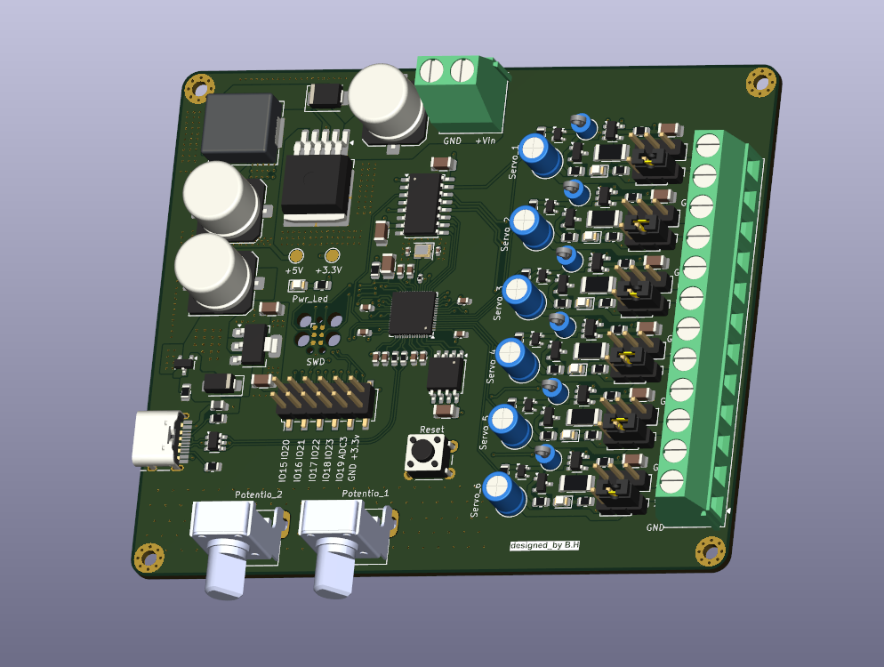 |  |  |
| Parameter | Value |
|---|---|
| MCU | Raspberry Pi RP2040 — Dual-core ARM Cortex-M0+ @ 133 MHz |
| Flash | 16MB W25Q16JV55 QSPI |
| Servo Channels | 6 independent, PIO-generated PWM |
| PWM Frequency | 50 Hz · 500–2500 µs pulse range |
| PWM Jitter | < 1 µs (PIO hardware, zero CPU involvement) |
| Current Sense | Per-channel INA180 amplifier (×20 gain, 10 mΩ shunt) |
| Peak Current | 10A total across all 6 channels |
| Input Voltage | 6V – 24V VIN + USB-C 5V |
| PCB | 4-Layer, KiCad |
| Firmware | MicroPython · C++ Pico SDK |
| License | CERN Open Hardware License v2 |
Traditional servo controllers simply send PWM signals. This board goes further:
MEASURE → ANALYZE → REACTEvery servo channel has a dedicated current sense amplifier. The RP2040 reads all six channels through a 74HC4051 analog multiplexer, continuously estimating torque, detecting collisions, and triggering per-channel shutdowns — all in real time.
GPIO 0–5 → Servo Enable (P-MOS high-side switches)
GPIO 6–11 → Servo PWM (PIO state machine outputs)
| GPIO | Net Name | Type | Connected To | Description |
|---|---|---|---|---|
| GPIO 0 | servo1_EN | GPIO OUT | AO3401A Gate Ch1 | High-side MOSFET enable — active HIGH |
| GPIO 1 | servo2_EN | GPIO OUT | AO3401A Gate Ch2 | High-side MOSFET enable — active HIGH |
| GPIO 2 | servo3_EN | GPIO OUT | AO3401A Gate Ch3 | High-side MOSFET enable — active HIGH |
| GPIO 3 | servo4_EN | GPIO OUT | AO3401A Gate Ch4 | High-side MOSFET enable — active HIGH |
| GPIO 4 | servo5_EN | GPIO OUT | AO3401A Gate Ch5 | High-side MOSFET enable — active HIGH |
| GPIO 5 | servo6_EN | GPIO OUT | AO3401A Gate Ch6 | High-side MOSFET enable — active HIGH |
| GPIO 6 | servo1_PWM | PIO OUT | Servo 1 signal wire | 50 Hz PIO PWM — sub-µs jitter |
| GPIO 7 | servo2_PWM | PIO OUT | Servo 2 signal wire | 50 Hz PIO PWM |
| GPIO 8 | servo3_PWM | PIO OUT | Servo 3 signal wire | 50 Hz PIO PWM |
| GPIO 9 | servo4_PWM | PIO OUT | Servo 4 signal wire | 50 Hz PIO PWM |
| GPIO 10 | servo5_PWM | PIO OUT | Servo 5 signal wire | 50 Hz PIO PWM |
| GPIO 11 | servo6_PWM | PIO OUT | Servo 6 signal wire | 50 Hz PIO PWM |
| GPIO 12 | S0 (MUX) | GPIO OUT | 74HC4051 Pin 11 | MUX address bit 0 |
| GPIO 13 | S1 (MUX) | GPIO OUT | 74HC4051 Pin 10 | MUX address bit 1 |
| GPIO 14 | S2 (MUX) | GPIO OUT | 74HC4051 Pin 9 | MUX address bit 2 |
| GPIO 18 | POT_1 | ADC0 IN | RV1 wiper | Manual Joint 1 input (0–3.3V = 0°–180°) |
| GPIO 19 | POT_2 | ADC1 IN | RV2 wiper | Manual Joint 2 input |
| GPIO 26 | MUX_A | GPIO OUT | 74HC4051 Pin 11 | MUX address line A |
| GPIO 27 | MUX_B | GPIO OUT | 74HC4051 Pin 10 | MUX address line B |
| GPIO 28 | MUX_C | GPIO OUT | 74HC4051 Pin 9 | MUX address line C |
| GPIO 29 | ISNS_ADC | ADC3 IN | 74HC4051 Common (Z) | Reads selected channel current sense voltage |
| USB-C | USB_DP/DM | USB 1.1 | USB-C connector | UF2 bootloader + CDC serial debug |
| SWD | SWCLK/SWDIO | DEBUG | SWD header (JB) | ARM Serial Wire Debug |
| Layer | Function | Details |
|---|---|---|
| Layer 1 — Top | Signal + Components | All SMD placement, fine-pitch routing (MCU, INA180, MUX) |
| Layer 2 — GND | Solid ground plane | Low-impedance return path, EMI shielding, heat spreading |
| Layer 3 — Power | Split power planes | 3.3V (MCU/sensors) · 5V (buck) · VIN (servo rails) |
| Layer 4 — Bottom | High-current traces | Servo power delivery, secondary signal routing |
A 4-layer design is essential here — with 6 servo channels switching simultaneously and up to 10A peak current, a 2-layer board would suffer from unacceptable EMI coupling and resistive heating.
The fundamental relationship exploited by this board:
τ = Kₜ × IA DC motor's torque is directly proportional to its armature current. Kₜ is the motor's torque constant (Nm/A). By measuring current through the INA180 shunt amplifiers, we measure torque — without any mechanical sensor.
I (servo current)
  → V_shunt = I × R_shunt          (Ohm's Law across 10mΩ shunt)
  → V_out = V_shunt × 20           (INA180 ×20 amplification)
  → ADC = (V_out / 3.3V) × 65535  (RP2040 12-bit ADC)
  → I = (ADC / 65535 × 3.3) / (20 × 0.01)
At 2.5A (overload threshold): V_shunt = 25mV → V_out = 500mV — well within ADC range.
Resolution: ~0.25 mA per LSB → ~0.02 mNm torque resolution per LSB.
θ° = (t_pulse − 500µs) / 2000µs × 180°| Pulse Width | Angle |
|---|---|
| 500 µs | 0° |
| 1500 µs | 90° (centre) |
| 2500 µs | 180° |
The RP2040's PIO state machines generate these pulses in hardware — completely independent of the CPU clock, eliminating software-induced jitter that corrupts positional accuracy.
Hardware PWM slices share a clock divider. Reprogramming multiple channels simultaneously causes brief glitches. PIO state machines run from dedicated instruction memory, each executing its PWM loop independently — giving 6 perfectly phase-stable signals while freeing both CPU cores for inverse kinematics or vision tasks.
When the arm hits an obstacle, the motor stalls. A stalled motor draws its locked-rotor current — far above normal running current:
Normal:  I ≈ 0.3–0.8 A  →  τ ≈ 0.025–0.068 Nm
Stall:   I → 2–4 A      →  τ → 0.17–0.34 Nm  ← triggers shutdown
The ADC scans all 6 channels continuously. A torque spike is detected within one scan cycle (~1 ms). The P-MOSFET cuts power within a single GPIO toggle (~10 ns).
| Feature | Description |
|---|---|
| Torque Estimation | τ = Kₜ × I, live on all 6 joints, ~0.02 mNm resolution |
| Collision Detection | Configurable torque threshold (default 0.20 Nm) triggers per-joint shutdown |
| Overcurrent Protection | Sustained current > 2.5A sets latching fault, cuts P-MOSFET |
| Emergency Stop | All 6 channels cut simultaneously via single function call |
| Smooth Motion | Interpolated moves with per-step collision check |
| Power Sequencing | Staggered joint enable (100ms delay) prevents inrush brownout |
| Fault Latch | Fault persists until software reset — prevents repeated thermal stress |
# robotic_arm_controller.py
# GPIO 0-5  → Servo ENABLE (P-MOS high-side switches)
# GPIO 6-11 → Servo PWM    (PIO state machines)
import rp2, machine, time

SERVO_EN_PINS  = [0, 1, 2, 3, 4, 5]
SERVO_PWM_PINS = [6, 7, 8, 9, 10, 11]
MUX_SEL_PINS   = [12, 13, 14]
ADC_ISNS_PIN   = 29
POT1_PIN, POT2_PIN = 18, 19

SERVO_MIN_US = 500
SERVO_MAX_US = 2500
ISNS_GAIN    = 20
SHUNT_R      = 0.010
OVERLOAD_A   = 2.5
KT_NM_PER_A  = 0.085
COLLISION_NM = 0.20

@rp2.asm_pio(sideset_init=rp2.PIO.OUT_LOW)
def servo_pwm_pio():
    pull(block)          .side(0)
    mov(x, osr)
label("high_loop")1. Power the board Connect VIN (6–24V) to the screw terminal. Set jumpers JP1–JP6:
2. Flash firmware
Hold BOOT on the back, press RESET. A drive named RPI-RP2 appears. Drag your .uf2 file onto it. Board reboots and runs automatically.
3. Test with potentiometers RV1 and RV2 control Joint 1 and Joint 2 by default. Rotate to verify servo response before connecting the full arm.
4. Monitor over serial
Open any terminal at 115200 baud on the USB-C port. arm.status() prints a live table of angle, current, torque, and fault state for all 6 joints.
5. Tune collision thresholds
Run the arm freely and log status() output. Set COLLISION_NM to ~1.5–2× the maximum torque observed during normal free movement.
6. Extend with C++ for performance Run motion control on Core 0 and current sensing on Core 1 for fully parallel deterministic operation. Core 1 can achieve scan rates exceeding 10 kHz — enabling sub-millisecond collision response.
Released under the CERN Open Hardware Licence Version 2 — Strongly Reciprocal (CERN-OHL-S v2).
Free to study, modify, manufacture, and distribute — derivatives must remain open source.
| Qty | Value | Footprint | References |
|---|---|---|---|
| 13 | 10k | Resistor_SMD:R_0805_2012Metric | R3, R5, R7, R9, R11, R13, R16, R18, R20, R22, R24, R28, R29 |
| 12 | 220 | Resistor_SMD:R_0805_2012Metric | R4, R8, R12, R17, R21, R27, R33, R34, R35, R36, R37, R38 |
| 7 | AO3401A | Package_TO_SOT_SMD:SOT-23 | Q1, Q2, Q3, Q4, Q5, Q6, Q7 |
| 7 | LED | LED_SMD:LED_0805_2012Metric | D3, D6, D7, D8, D9, D10, D11 |
| 6 | 0.1 | Resistor_SMD:R_2010_5025Metric | R2, R6, R10, R14, R19, R23 |
| 6 | 0.1u | Capacitor_SMD:C_0603_1608Metric | C7, C8, C9, C10, C11, C12 |
| 6 | 100u | Capacitor_THT:C_Radial_D5.0mm_H7.0mm_P2.00mm | C2, C18, C20, C22, C24, C26 |
| 6 | C | Capacitor_SMD:C_1206_3216Metric | C17, C19, C21, C23, C25, C27 |
| 6 | Conn_01x03_Pin | Connector_PinHeader_2.54mm:PinHeader_1x03_P2.54mm_Vertical | J1, J2, J3, J4, J6, J7 |
| 6 | INA180A1 | Package_TO_SOT_SMD:SOT-23-5 | U5, U8, U10, U13, U15, U17 |
| 6 | Jumper_3_Open | Connector_PinHeader_2.54mm:PinHeader_1x03_P2.54mm_Vertical | JP1, JP2, JP3, JP4, JP5, JP6 |
| 6 | PC817 | Package_TO_SOT_SMD:Analog_KS-4 | U4, U7, U9, U12, U14, U16 |
| 6 | TestPoint | TestPoint:TestPoint_Keystone_5005-5009_Compact | TP3, TP4, TP5, TP6, TP7, TP8 |
| 5 | 0.1u | Capacitor_SMD:C_1206_3216Metric | C6, C28, C29, C30, C37 |
| 4 | MountingHole_Pad | MountingHole:MountingHole_2.5mm_Pad_Via | H1, H2, H3, H4 |
| 2 | 100n | Capacitor_SMD:C_0603_1608Metric | C15, C16 |
| 2 | 12pF | Capacitor_SMD:C_0402_1005Metric | C4, C33 |
| 2 | 1u | Capacitor_SMD:C_0603_1608Metric | C13, C14 |
| 2 | 27 | Resistor_SMD:R_0603_1608Metric | R30, R31 |
| 2 | 5.1K | Resistor_SMD:R_0805_2012Metric | R15, R25 |
| 2 | R_Potentiometer | New_Library:TRIM_PT01-B115D-B103 | RV1, RV2 |
| 2 | TestPoint | TestPoint:TestPoint_Pad_D2.0mm | TP1, TP2 |
| 1 | 10u | Capacitor_SMD:C_1206_3216Metric | C36 |
| 1 | 10u | Capacitor_SMD:C_Elec_10x10.2 | C35 |
| 1 | 12MHz(10ppm) | Crystal:Crystal_SMD_2520-4Pin_2.5x2.0mm | Y2 |
| 1 | 1K | Resistor_SMD:R_0805_2012Metric | R1 |
| 1 | 1N5822 | Diode_SMD:D_SMB | D2 |
| 1 | 1k | Resistor_SMD:R_0402_1005Metric | R26 |
| 1 | 1k | Resistor_SMD:R_0805_2012Metric | R32 |
| 1 | 220u | Capacitor_SMD:C_Elec_10x10.2 | C34 |
| 1 | 33u | Inductor_SMD:L_Bourns_SRP1050WA | L2 |
| 1 | 680u | Capacitor_SMD:C_Elec_10x10.2 | C32 |
| 1 | 74HC4051 | Package_SO:SOIC-16W_5.3x10.2mm_P1.27mm | U6 |
| 1 | AMS1117-3.3 | Package_TO_SOT_SMD:SOT-223-3_TabPin2 | U19 |
| 1 | Conn_02x06_Odd_Even | Connector_PinHeader_2.54mm:PinHeader_2x06_P2.54mm_Vertical_SMD | J11 |
| 1 | Conn_ARM_SWD_TagConnect_TC2030 | Connector:Tag-Connect_TC2030-IDC-FP_2x03_P1.27mm_Vertical | J8 |
| 1 | FerriteBead | Inductor_SMD:L_0805_2012Metric | FB2 |
| 1 | LM2596S-5 | Package_TO_SOT_SMD:TO-263-5_TabPin3 | U3 |
| 1 | RP2040 | Package_DFN_QFN:QFN-56-1EP_7x7mm_P0.4mm_EP3.2x3.2mm | U1 |
| 1 | SS34 | Diode_SMD:D_SMA | D1 |
| 1 | SW_Push | Button_Switch_THT:SW_PUSH_6mm_H5mm | SW1 |
| 1 | Screw_Terminal_01x02 | TerminalBlock_Phoenix:TerminalBlock_Phoenix_MKDS-1,5-2-5.08_1x02_P5.08mm_Horizontal | J9 |
| 1 | Screw_Terminal_01x12 | TerminalBlock_Phoenix:TerminalBlock_Phoenix_MKDS-1,5-12-5.08_1x12_P5.08mm_Horizontal | J10 |
| 1 | USBLC6-2SC6 | Package_TO_SOT_SMD:SOT-23-6 | U11 |
| 1 | USB_C_Receptacle_USB2.0_14P | Connector_USB:USB_C_Receptacle_HRO_TYPE-C-31-M-12 | J5 |
| 1 | W25Q16JVSS | Package_SO:SOIC-8_5.3x5.3mm_P1.27mm | U2 |
krishchan007/DUT_Interface_board_v0.2
v0.2 of DUT interface board with significant changes in layout, architecture etc.

nthclrd/picflash
Programmeur PIC open source en Rust : remplace MPLAB IPE/XC8 pour les PIC16, pilote les PICkit 4/5/Basic ou une carte RP2040 maison (KiCad)

justinlindh/digits
Encrypted retro phone network — private VoIP over vintage desk phones


Scalable-Open-Source-Labs/Mass-Spring-Damper-SysID-Lab
An open source Mass-Spring-Damper to assist with teaching System Identification


dexus1337/automotive-gateway
An automotive-grade, multi-protocol vehicle network interface, Man-in-the-Middle (MitM) filter, and wireless telemetry gateway
It measures 99 × 84 mm and has 4 copper layers, 1.6 mm thick.
140 parts, built around the RP2040, LM2596S-5.0, W25Q16JVSSIQ and 74HC4051. The full list of its parts is on this page, with links to each part's symbol and footprint where PCBKit's library has them.
From the bejaouihamza/robotic_arm_controller repository on GitHub, at the commit this page was made from: the board is robotic_arm_controller.kicad_pcb and its schematic robotic_arm_controller.kicad_sch. PCBKit opens the board in the browser, with nothing to install.
Its repository states no licence, so its author keeps all rights: ask bejaouihamza before reusing the design.