2 layers167.8 × 200.6 mm
Random Jazz Generator
telec16/modular-synth
Little side project, don't expect much updates.
132 parts16

 bazsimarkus/a277d-led-tachometer
An analog LED tachometer controlled by an East German A277D chip (clone of UAA180), featuring an integrated ATtiny13A-based digital ignition pulse generator for testing.
A277d led tachometer is an open-source printed circuit board by bazsimarkus, from the bazsimarkus/a277d-led-tachometer repository on GitHub. It is a 2-layer board of 140 × 60 mm with 61 parts on 39 nets, routed with 287 tracks and 0 vias.
It is built around the ATTINY13A-PU, L7805 and BC547, with the BC557 among its other parts. Its parts include 15 diodes, 11 resistors, 9 capacitors, 8 connectors and 4 ICs. It belongs with the AVR (ATmega, ATtiny) boards of this library.


An analog LED tachometer controlled by an East German A277D chip (clone of UAA180), featuring an integrated ATtiny13A-based digital ignition pulse generator for testing.
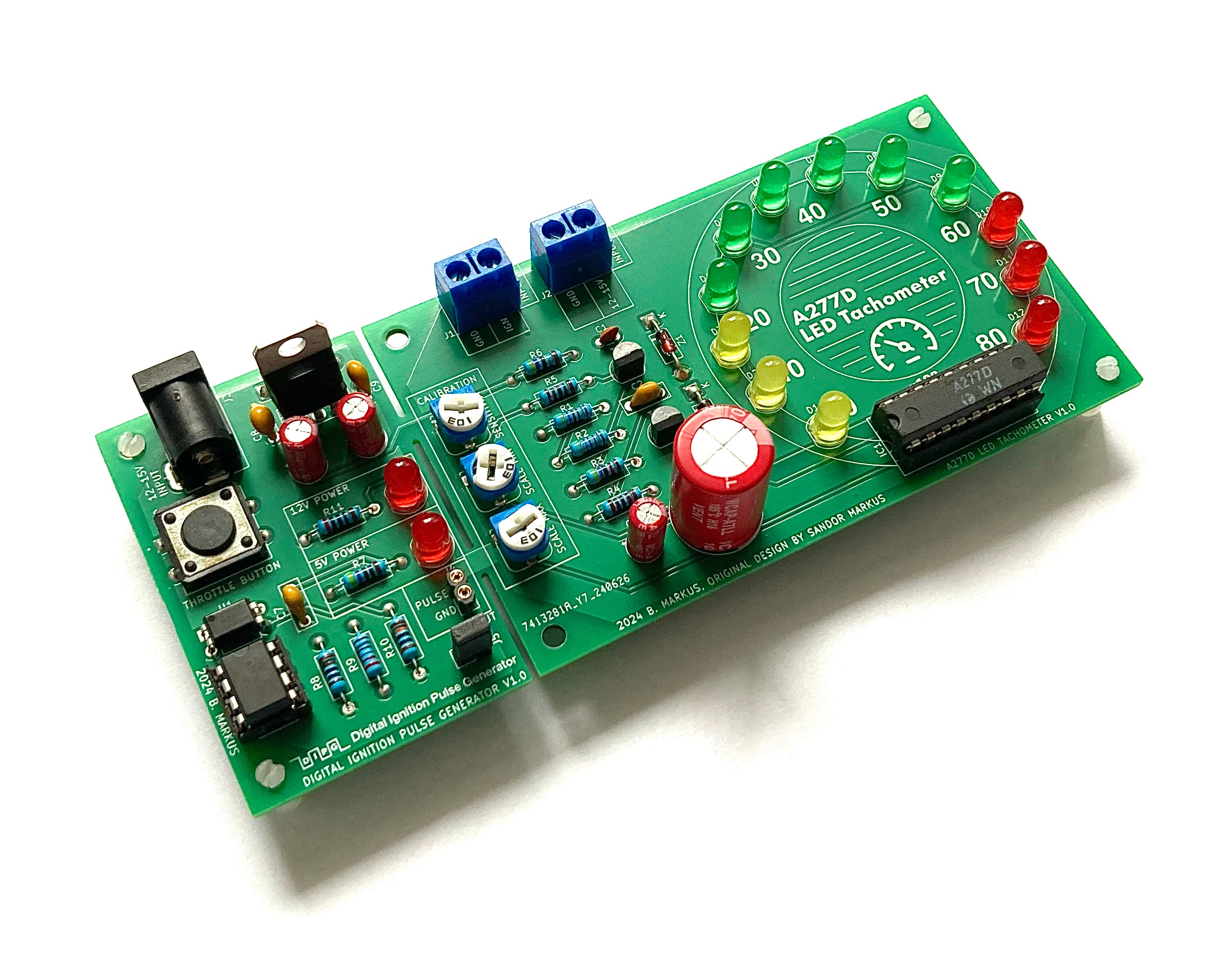
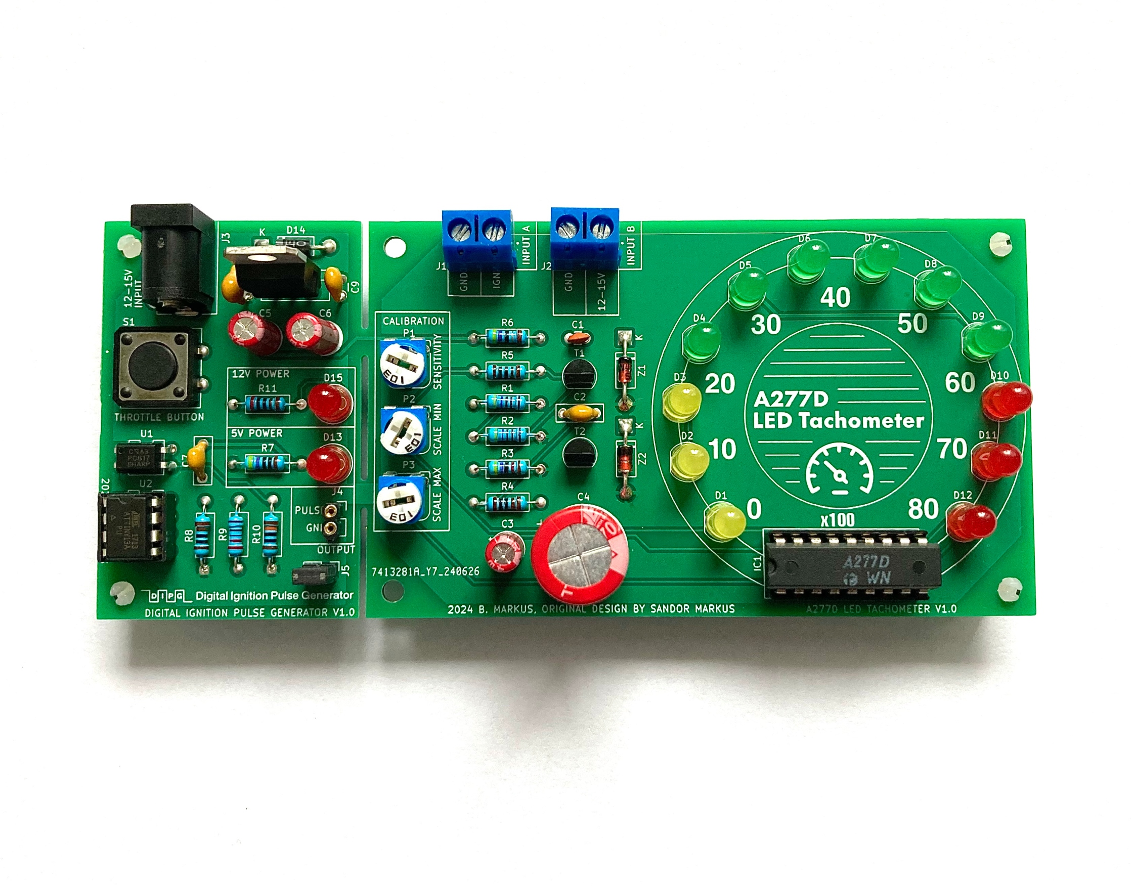
This project combines two circuit boards:
The pulse generator board is attached to the left side of the main board and can be broken off if the tachometer is to be installed in an actual vehicle.
This circuit has a special history spanning nearly four decades:
In the late 1980s, my father designed this tachometer for his LADA 2105, which lacked a factory-installed tachometer. In 2024, I discovered his original hand-drawn sketches and PCB design prototypes, which inspired me to rebuild this circuit using modern CAD tools while staying true to the original design philosophy.
The base circuit was inspired by a design published on page 213 of the 1987 edition of Rádiótechnika évkönyve (Yearbook of Radiotechnics). Rádiótechnika was Hungary's longest-running electronics and radio amateur magazine (mid-20th century - 2021), serving as a central resource for hobbyists, engineers, and radio amateurs.
The LED color sequence (yellow-green-red) follows the original design, even though green-yellow-red might be more conventional today.
Note: A relevant excerpt from the original 1987 publication is included in docs/radiotechnika.yearbook.hu1987-203-225.pdf.
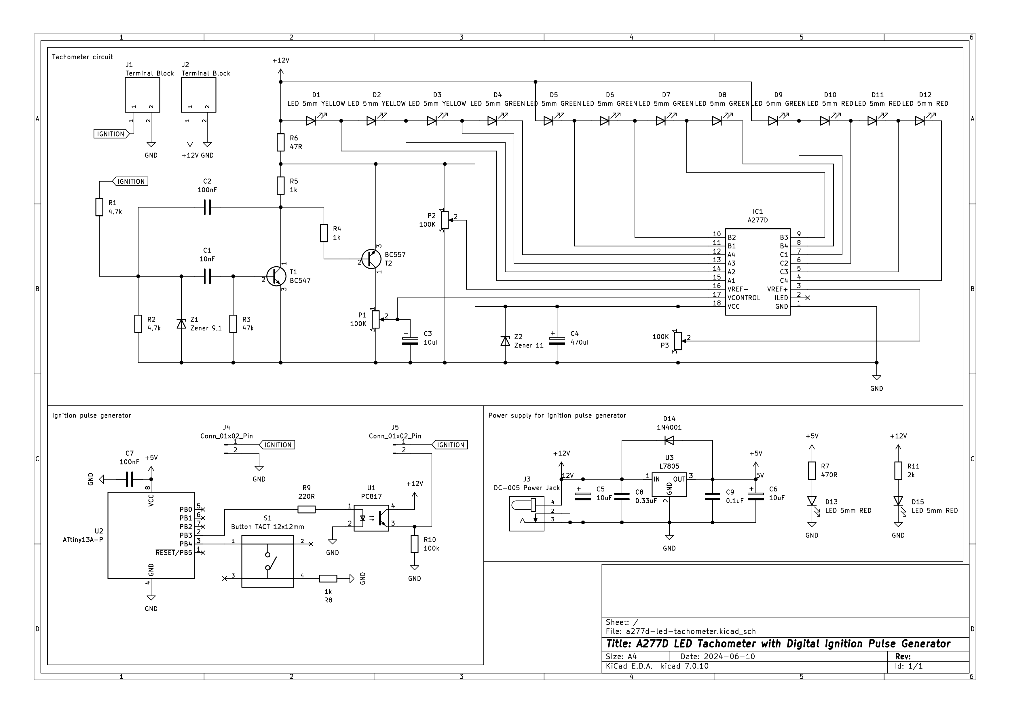
The main tachometer circuit processes ignition pulses and drives a 12-LED bar graph display.
Key Components:
Power Requirements:
The pulse generator uses an ATtiny13A microcontroller to simulate engine ignition pulses.
Key Components:
ATtiny13A Pinout:
         ATtiny13A (DIP-8)
         ┌─────┬─┬─────┐
 RESET ──┤1 PB5   VCC 8├── +5V
    NC ──┤2 PB3   PB2 7├── NC (SCK)
BUTTON ──┤3 PB4   PB1 6├── NC (MISO)
   GND ──┤4 GND   PB0 5├── NC (MOSI)
         └─────────────┘
USBasp Programmer Pinout:
    USBasp 10-pin IDC
    ┌─────────────┐
  ──┤1 MOSI  VCC 2├── +5V
  ──┤3 NC    GND 4├── GND
  ──┤5 RESET GND 6├── GND
  ──┤7 SCK   GND 8├── GND
  ──┤9 MISO  GND10├── GND
    └─────────────┘
Programming Connection:
| USBasp Pin | ATtiny13A Pin | Function |
|---|---|---|
| VCC (2) | 8 (VCC) | +5V |
| GND (4/6/8/10) | 4 (GND) | Ground |
| RESET (5) | 1 (RESET) | Reset |
| SCK (7) | 7 (PB2) | Clock |
| MISO (9) | 6 (PB1) | MISO |
| MOSI (1) | 5 (PB0) | MOSI |
| Item | Qty | Reference(s) | Value | Footprint | Notes |
|---|---|---|---|---|---|
| 1 | 1 | C1 | 10nF | C_Disc_D3.0mm | Ceramic capacitor |
| 2 | 2 | C2, C7 | 100nF | C_Disc_D7.0mm | Ceramic capacitor |
| 3 | 3 | C3, C5, C6 | 10µF | CP_Radial_D5.0mm | Electrolytic |
| 4 | 1 | C4 | 470µF | CP_Radial_D13.0mm | Electrolytic |
| 5 | 1 | C8 | 0.33µF | C_Disc_D3.0mm | Ceramic capacitor |
| 6 | 1 | C9 | 0.1µF | C_Disc_D3.0mm | Ceramic capacitor |
| 7 | 3 | D1, D2, D3 | LED 5mm YELLOW | LED_D5.0mm | Yellow LEDs |
| 8 | 6 | D4-D9 | LED 5mm GREEN | LED_D5.0mm | Green LEDs |
| 9 | 5 | D10-D13, D15 | LED 5mm RED | LED_D5.0mm | Red LEDs |
| 10 | 1 | D14 | 1N4001 | DO-41 | Rectifier diode |
| 11 | 1 | IC1 | A277D | DIP-18 | LED driver (UAA180 clone) |
| 12 | 2 | J1, J2 | Terminal Block | KF301-2P | 5mm pitch |
| 13 | 1 | J3 | DC-005 | Power Jack | 2.1mm barrel jack |
| 14 | 1 | J4 | Conn_01x02 | PinSocket 2.54mm | Female header |
| 15 | 1 | J5 | Conn_01x02 | PinHeader 2.54mm | Male header |
| 16 | 3 | P1, P2, P3 | 100kΩ | Trimpot RM-065 | Calibration trimmers |
| 17 | 2 | R1, R2 | 4.7kΩ | Axial DIN0207 | 1/4W resistor |
| 18 | 1 | R3 | 47kΩ | Axial DIN0207 | 1/4W resistor |
| 19 | 3 | R4, R5, R8 | 1kΩ | Axial DIN0207 | 1/4W resistor |
| 20 | 1 | R6 | 47Ω | Axial DIN0207 | 1/4W resistor |
| 21 | 1 | R7 | 470Ω | Axial DIN0207 | 1/4W resistor |
| 22 | 1 | R9 | 220Ω | Axial DIN0207 | 1/4W resistor |
| 23 | 1 | R10 | 100kΩ | Axial DIN0207 | 1/4W resistor |
| 24 | 1 | R11 | 2kΩ | Axial DIN0207 | 1/4W resistor |
| 25 | 1 | S1 | Button TACT | 12×12mm | Momentary pushbutton |
| 26 | 1 | T1 | BC547 | TO-92 | NPN transistor |
| 27 | 1 | T2 | BC557 | TO-92 | PNP transistor |
| 28 | 1 | U1 | PC817 | DIP-4 | Optocoupler |
| 29 | 1 | U2 | ATtiny13A-P | DIP-8 | Microcontroller |
| 30 | 1 | U3 | L7805 | TO-220 | 5V voltage regulator |
| 31 | 1 | Z1 | 9.1V Zener | DO-41 | Zener diode |
| 32 | 1 | Z2 | 11V Zener | DO-41 | Zener diode |
Additional Hardware:
The tachometer circuit operates as follows:
Input Signal Conditioning: The ignition pulse from J1 or the pulse generator passes through R1, C1, and the transistor pair (T1, T2) for signal conditioning and buffering. Zener diodes Z1 and Z2 provide voltage clamping and protection.
A277D LED Driver: The conditioned signal feeds into IC1 (A277D), which converts the frequency to an analog voltage and drives the LED bar graph proportionally. The chip includes internal comparators that illuminate LEDs based on the input frequency.
Calibration:
LED Display: The 12 LEDs illuminate sequentially:
The circuit is designed for 4-cylinder engines but can be adapted for other configurations by adjusting the sensitivity trimmer.
The ATtiny13A firmware (a277d-led-tachometer.ino) generates a variable-frequency square wave:
Frequency Generation: A square wave is output on PB3 (pin 2) with adjustable frequency between 60-200 Hz, simulating engine speeds from idle to high RPM.
User Control: Button S1 on PB4 (pin 3) acts as a "throttle":
Precise Timing: The firmware uses micros() for accurate frequency generation and smooth frequency transitions.
Signal Isolation: The square wave passes through optocoupler U1 (PC817), providing:
Output Points:
Firmware Parameters:
#define MIN_FREQ 60              // Idle frequency (Hz)
#define MAX_FREQ 200             // Maximum frequency (Hz)
#define FREQ_CHANGE_SPEED 200 // Transition rate (Hz/s)Hardware:
Software:
Solder components following the schematic and PCB layout:
Inspect for shorts and cold solder joints before applying power
Test voltages:
If the USBasp is not recognized:
https://mcudude.github.io/MicroCore/package_MCUdude_MicroCore_index.jsonGo to Tools menu and select:
Connect the ATtiny13A on a breadboard to the USBasp following the pinout diagram above. Ensure the chip is powered with 5V.
a277d-led-tachometer.ino in Arduino IDEExpected Output:
Sketch uses 672 bytes (65%) of program storage space. Maximum is 1024 bytes.
Global variables use 18 bytes (28%) of dynamic memory, leaving 46 bytes for local variables.The tachometer requires calibration for accurate RPM display:
Note: For engines other than 4-cylinder, you may need to adjust component values (R3, C1) or use an external frequency divider.
With the pulse generator attached:
| Problem | Possible Cause | Solution |
|---|---|---|
| No LEDs illuminate | No power | Check 12V supply, fuse, polarity |
| No 5V at U2 pin 8 | U3 failure or incorrect wiring | Check U3, C5, C6, D14 |
| Status LEDs don't light | LED polarity reversed | Check D13, D15 orientation |
| Pulse generator doesn't work | ATtiny13A not programmed | Reprogram with correct fuses |
| Button does nothing | Wrong pin or bad solder joint | Check S1, R8, U2 pin 3 connection |
| No LED response to pulses | Signal not reaching IC1 | Check J5 jumper, U1, T1, T2, capacitors |
| LEDs always full or empty | Calibration issue | Adjust P1, P2, P3 trimmers |
| Erratic LED behavior | Noisy input signal | Add capacitance at J1, check grounding |
| USBasp not recognized | Driver issue (Windows) | Install drivers with Zadig |
| Upload fails | Wrong programmer settings | Select "USBasp slow" or use "-B32" flag |
Common Arduino IDE Errors:
Tachometer:
Pulse Generator:
PCB:
Questions or issues? Open an issue on GitHub or feel free to write me!
Want to build one? Share your build photos and experiences - I'd love to see them!
| Qty | Value | Footprint | References |
|---|---|---|---|
| 6 | LED 5mm GREEN | StockLib:LED_D5.0mm_GREEN | D4, D5, D6, D7, D8, D9 |
| 6 | MountingHole_3.2mm_M3 | MountingHole:MountingHole_3.2mm_M3 | REF1, REF2, REF3, REF4, REF5, REF6 |
| 5 | LED 5mm RED | StockLib:LED_D5.0mm_RED | D10, D11, D12, D13, D15 |
| 4 | 1k | StockLib:R_1k_Axial_DIN0207 | R4, R5, R8, R11 |
| 3 | 100K | StockLib:Trimpot RM-065 | P1, P2, P3 |
| 3 | 10uF | Capacitor_THT:CP_Radial_D5.0mm_P2.00mm | C3, C5, C6 |
| 3 | LED 5mm YELLOW | StockLib:LED_D5.0mm_YELLOW | D1, D2, D3 |
| 3 | LOGO | LOGO | G***, G1, G2 |
| 2 | 100nF | StockLib:C_100nF_L7.0mm_W2.5mm_P5.00mm | C2, C7 |
| 2 | 4,7k | Resistor_THT:R_Axial_DIN0207_L6.3mm_D2.5mm_P10.16mm_Horizontal | R1, R2 |
| 2 | Terminal Block | StockLib:Terminal Block KF301-2P | J1, J2 |
| 1 | 0.1uF | Capacitor_THT:C_Disc_D3.0mm_W1.6mm_P2.50mm | C9 |
| 1 | 0.33uF | Capacitor_THT:C_Disc_D3.0mm_W1.6mm_P2.50mm | C8 |
| 1 | 100k | Resistor_THT:R_Axial_DIN0207_L6.3mm_D2.5mm_P10.16mm_Horizontal | R10 |
| 1 | 10nF | Capacitor_THT:C_Disc_D3.0mm_W1.6mm_P2.50mm | C1 |
| 1 | 1N4001 | Diode_THT:D_DO-41_SOD81_P10.16mm_Horizontal | D14 |
| 1 | 220R | Resistor_THT:R_Axial_DIN0207_L6.3mm_D2.5mm_P10.16mm_Horizontal | R9 |
| 1 | 470R | StockLib:R_470_Axial_DIN0207 | R7 |
| 1 | 470uF | Capacitor_THT:CP_Radial_D13.0mm_P5.00mm | C4 |
| 1 | 47R | Resistor_THT:R_Axial_DIN0207_L6.3mm_D2.5mm_P10.16mm_Horizontal | R6 |
| 1 | 47k | Resistor_THT:R_Axial_DIN0207_L6.3mm_D2.5mm_P10.16mm_Horizontal | R3 |
| 1 | A277D | Package_DIP:DIP-18_W7.62mm_Socket | IC1 |
| 1 | ATtiny13A-P | Package_DIP:DIP-8_W7.62mm | U2 |
| 1 | BC547 | Package_TO_SOT_THT:TO-92_Inline | T1 |
| 1 | BC557 | Package_TO_SOT_THT:TO-92_Inline | T2 |
| 1 | Button TACT 12x12mm | StockLib:Button TACT 12x12mm | S1 |
| 1 | Conn_01x02_Pin | Connector_PinSocket_2.54mm:PinSocket_1x02_P2.54mm_Vertical | J4 |
| 1 | Conn_01x02_Pin | Connector_PinHeader_2.54mm:PinHeader_1x02_P2.54mm_Vertical | J5 |
| 1 | DC-005 Power Jack | StockLib:DC-005 Power Jack | J3 |
| 1 | L7805 | Package_TO_SOT_THT:TO-220-3_Vertical | U3 |
| 1 | PC817 | Package_DIP:DIP-4_W7.62mm | U1 |
| 1 | Zener 11 | Diode_THT:D_DO-41_SOD81_P10.16mm_Horizontal | Z2 |
| 1 | Zener 9,1 | Diode_THT:D_DO-41_SOD81_P10.16mm_Horizontal | Z1 |
telec16/modular-synth
Little side project, don't expect much updates.


punkfab/pcb-corpus
235 real KiCad boards from open-source hardware repositories, prepared as a placement and routing benchmark


bananu7/ktmtps
All the stuff related to re-engineering the Throttle Position Sensor (TPS) of a KTM 990/950


dotnet/iot
This repo includes .NET Core implementations for various IoT boards, chips, displays and PCBs.

robsonsmartins/usbflashprog
A memory device programmer (Flash/EPROM/E2PROM) board and software, connected to PC by USB port.
It measures 140 × 60 mm and has 2 copper layers, 1.6 mm thick.
61 parts, built around the ATTINY13A-PU, L7805, BC547 and BC557. The full list of its parts is on this page, with links to each part's symbol and footprint where PCBKit's library has them.
From the bazsimarkus/a277d-led-tachometer repository on GitHub, at the commit this page was made from: the board is schematic/a277d-led-tachometer.kicad_pcb and its schematic schematic/a277d-led-tachometer.kicad_sch. PCBKit opens the board in the browser, with nothing to install.
Its repository states no licence, so its author keeps all rights: ask bazsimarkus before reusing the design.