
8 layers
FIRM v1.1
NCSU-High-Powered-Rocketry-Club/FIRM-KiCad
Full and open hardware design for FIRM
108 parts1MIT

The board is designed around a high-performance flight-control MCU and uses three independent SPI-connected IMUs for motion sensing.
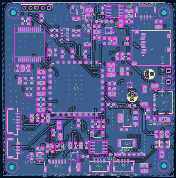
Aviyonik is an open-source printed circuit board by basarbinici, from the basarbinici/4-Layered-Flight-Controller-PCB repository on GitHub. It is a 4-layer board of 69.8 × 71.5 mm with 133 parts on 156 nets, routed with 1,384 tracks and 407 vias.
It is built around the TCAN1044VDRQ1, INA226AIDGST and MMC5983MA, with the MS5611-01BA03, MEM2061-01-188-00-A and LP5907MFX-1.8 among its other parts. Its parts include 65 capacitors, 31 resistors, 13 ICs, 10 connectors and 4 diodes. It belongs with the STM32 boards of this library.


The board is designed around a high-performance flight-control MCU and uses three independent SPI-connected IMUs for motion sensing.
Additional onboard sensors provide:
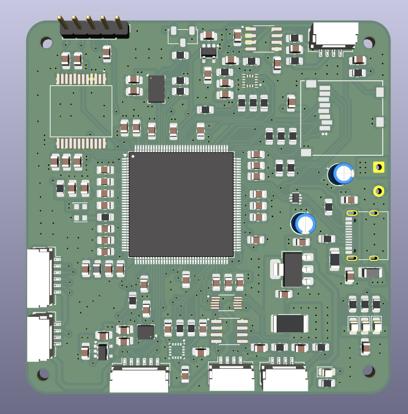
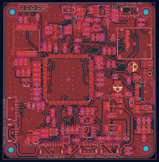
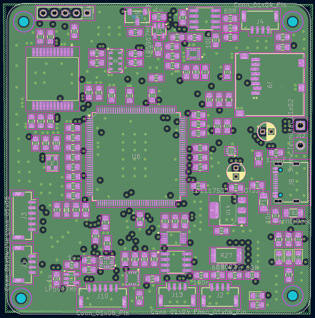
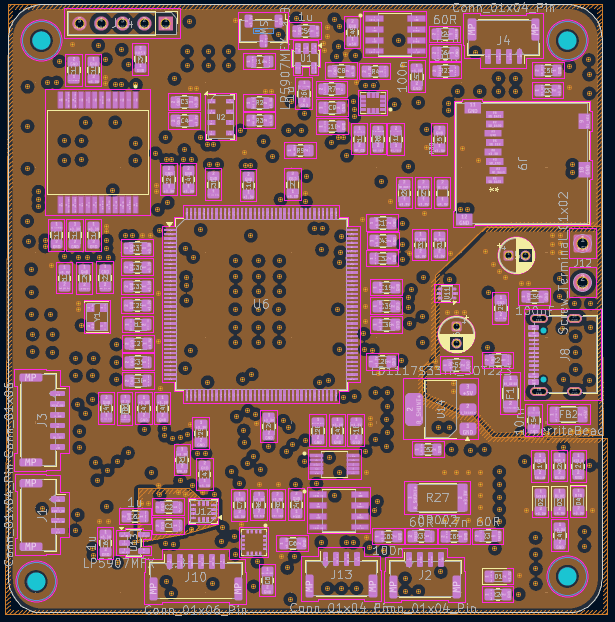
| Qty | Value | Footprint | References |
|---|---|---|---|
| 27 | 100nF | Capacitor_SMD:C_0805_2012Metric_Pad1.18x1.45mm_HandSolder | C3, C16, C17, C18, C21, C22, C23, C24, C25, C26, C27, C29, C31, C33, C34, C36 +11 |
| 8 | 100n | Capacitor_SMD:C_0805_2012Metric_Pad1.18x1.45mm_HandSolder | C1, C14, C15, C47, C48, C49, C53, C63 |
| 8 | 10K | Resistor_SMD:R_0805_2012Metric_Pad1.20x1.40mm_HandSolder | R1, R14, R28, R29, R30, R31, R32, R33 |
| 7 | 1u | Capacitor_SMD:C_0805_2012Metric_Pad1.18x1.45mm_HandSolder | C2, C11, C13, C59, C60, C61, C62 |
| 6 | 0R | Resistor_SMD:R_0805_2012Metric_Pad1.20x1.40mm_HandSolder | R4, R7, R8, R9, R10, R11 |
| 5 | 10nF | Capacitor_SMD:C_0805_2012Metric_Pad1.18x1.45mm_HandSolder | C8, C19, C20, C40, C54 |
| 5 | 1uF | Capacitor_SMD:C_0805_2012Metric_Pad1.18x1.45mm_HandSolder | C6, C30, C42, C45, C51 |
| 4 | 2.2uF | Capacitor_SMD:C_0805_2012Metric_Pad1.18x1.45mm_HandSolder | C10, C28, C32, C35 |
| 4 | 220 | Resistor_SMD:R_0805_2012Metric_Pad1.20x1.40mm_HandSolder | R19, R20, R21, R26 |
| 4 | 60R | Resistor_SMD:R_0805_2012Metric_Pad1.20x1.40mm_HandSolder | R22, R23, R34, R35 |
| 4 | Conn_01x04_Pin | Connector_JST:JST_GH_SM04B-GHS-TB_1x04-1MP_P1.25mm_Horizontal | J1, J2, J4, J13 |
| 4 | LED | LED_SMD:LED_0805_2012Metric_Pad1.15x1.40mm_HandSolder | D1, D2, D3, D4 |
| 4 | MountingHole | MountingHole:MountingHole_2.2mm_M2 | H1, H2, H3, H4 |
| 2 | 10uF | Capacitor_SMD:C_0805_2012Metric_Pad1.18x1.45mm_HandSolder | C5, C57 |
| 2 | 4.7k | Resistor_SMD:R_0805_2012Metric_Pad1.20x1.40mm_HandSolder | R5, R6 |
| 2 | 4.7n | Capacitor_SMD:C_0805_2012Metric_Pad1.18x1.45mm_HandSolder | C64, C65 |
| 2 | 4K7 | Resistor_SMD:R_0805_2012Metric_Pad1.20x1.40mm_HandSolder | R2, R3 |
| 2 | 5K1 | Resistor_SMD:R_0805_2012Metric_Pad1.20x1.40mm_HandSolder | R24, R25 |
| 2 | LP5907MFX-1.8 | Package_TO_SOT_SMD:SOT-23-5 | U1, U13 |
| 2 | TCAN1044VDRQ1 | Ayakizleri:SOIC127P599X175-8N | U7, U8 |
| 1 | 0.1uF | Capacitor_SMD:C_0805_2012Metric_Pad1.18x1.45mm_HandSolder | C9 |
| 1 | 0R002 | Resistor_SMD:R_2512_6332Metric | R27 |
| 1 | 10u | Capacitor_SMD:C_0805_2012Metric_Pad1.18x1.45mm_HandSolder | C12 |
| 1 | 10uF | Capacitor_THT:CP_Radial_D4.0mm_P2.00mm | C50 |
| 1 | 120R @100MHZ | Inductor_SMD:L_0805_2012Metric_Pad1.05x1.20mm_HandSolder | FB1 |
| 1 | 22R | Resistor_SMD:R_0805_2012Metric_Pad1.20x1.40mm_HandSolder | R13 |
| 1 | 4.7u | Capacitor_SMD:C_0805_2012Metric_Pad1.18x1.45mm_HandSolder | C52 |
| 1 | 4.7uF | Capacitor_THT:CP_Radial_D4.0mm_P2.00mm | C56 |
| 1 | 5R | Resistor_SMD:R_0805_2012Metric_Pad1.20x1.40mm_HandSolder | R12 |
| 1 | Conn_01x05 | Connector_PinHeader_2.54mm:PinHeader_1x05_P2.54mm_Vertical | J14 |
| 1 | Conn_01x06 | Connector_JST:JST_GH_SM06B-GHS-TB_1x06-1MP_P1.25mm_Horizontal | J3 |
| 1 | Conn_01x06_Pin | Connector_JST:JST_GH_SM06B-GHS-TB_1x06-1MP_P1.25mm_Horizontal | J10 |
| 1 | FerriteBead | Inductor_SMD:L_1206_3216Metric_Pad1.22x1.90mm_HandSolder | FB2 |
| 1 | ICM-42686-P | Ayakizleri:XDCR_ICM-42686-P | U4 |
| 1 | INA226AIDGST | Ayakizleri:SOP50P490X110-10N | U9 |
| 1 | ISM330IS | Package_LGA:LGA-14_3x2.5mm_P0.5mm_LayoutBorder3x4y | U12 |
| 1 | LD1117S33TR_SOT223 | Package_TO_SOT_SMD:SOT-223-3_TabPin2 | U14 |
| 1 | LOGO | Ayakizleri:ATA | G*** |
| 1 | MEM2061-01-188-00-A | Ayakizleri:MEM2061-01-188-00-A_GCT | J9 |
| 1 | MMC5983MA | Ayakizleri:PQFN50P300X300X100-16N | U3 |
| 1 | MS5611-01BA | Package_LGA:LGA-8_3x5mm_P1.25mm | U2 |
| 1 | PTC 2A/6V | Fuse:Fuse_1206_3216Metric_Pad1.42x1.75mm_HandSolder | F1 |
| 1 | SCH16T-K01-10 | Ayakizleri:XDCR_SCH16T-K01-10 | U5 |
| 1 | STM32H755ZITx | Package_QFP:LQFP-144_20x20mm_P0.5mm | U6 |
| 1 | SW_SPDT | Button_Switch_SMD:Nidec_Copal_CAS-120A | SW1 |
| 1 | Screw_Terminal_01x02 | Connector_Wire:SolderWire-0.5sqmm_1x02_P4.6mm_D0.9mm_OD2.1mm | J12 |
| 1 | USBLC6-2P6 | Package_TO_SOT_SMD:SOT-666 | U11 |
| 1 | USB_C_Receptacle_USB2.0_16P | Connector_USB:USB_C_Receptacle_G-Switch_GT-USB-7010ASV | J8 |
| 1 | XO32 | Oscillator:Oscillator_SMD_EuroQuartz_XO32-4Pin_3.2x2.5mm | Y1 |
It measures 69.8 × 71.5 mm and has 4 copper layers, 1.6 mm thick.
133 parts, built around the TCAN1044VDRQ1, INA226AIDGST, MMC5983MA and MS5611-01BA03. The full list of its parts is on this page, with links to each part's symbol and footprint where PCBKit's library has them.
From the basarbinici/4-Layered-Flight-Controller-PCB repository on GitHub, at the commit this page was made from: the board is aviyonik/aviyonik.kicad_pcb and its schematic aviyonik/aviyonik.kicad_sch. PCBKit opens the board in the browser, with nothing to install.
Its repository states no licence, so its author keeps all rights: ask basarbinici before reusing the design.
NCSU-High-Powered-Rocketry-Club/FIRM-KiCad
Full and open hardware design for FIRM


COSMIIC-Community/Externals-WL-Hardware
CAD files for Wireless Link (PCB and enclosure)


ManchesterStingerMotorsports/EV_Rear_SDC
Second half of Shutdown circuit logic and logging for states on the Johnson node that will sit at the back of the EV and act as a hat to the johnson node in addition to an IMU

MasaoC/GPS-TFT-Map_PONS
鳥人間コンテストに特化したGNSS誘導システム。人力飛行機のパイロットが使いやすいことを目標にした航法装置です。ハードとソフトをオープンソースで開発しています。

oro-os/link
The Oro OS CI/CD pipeline including PCBs, CAD files, firmware and server infrastructure
