2 layers54 × 12.5 mm
BrodBoost C2
axiometa/BrodBoost-C2
USB - C Breadboard Powersupply: BrodBoost-C
31 parts36CERN-OHL-S-2.0
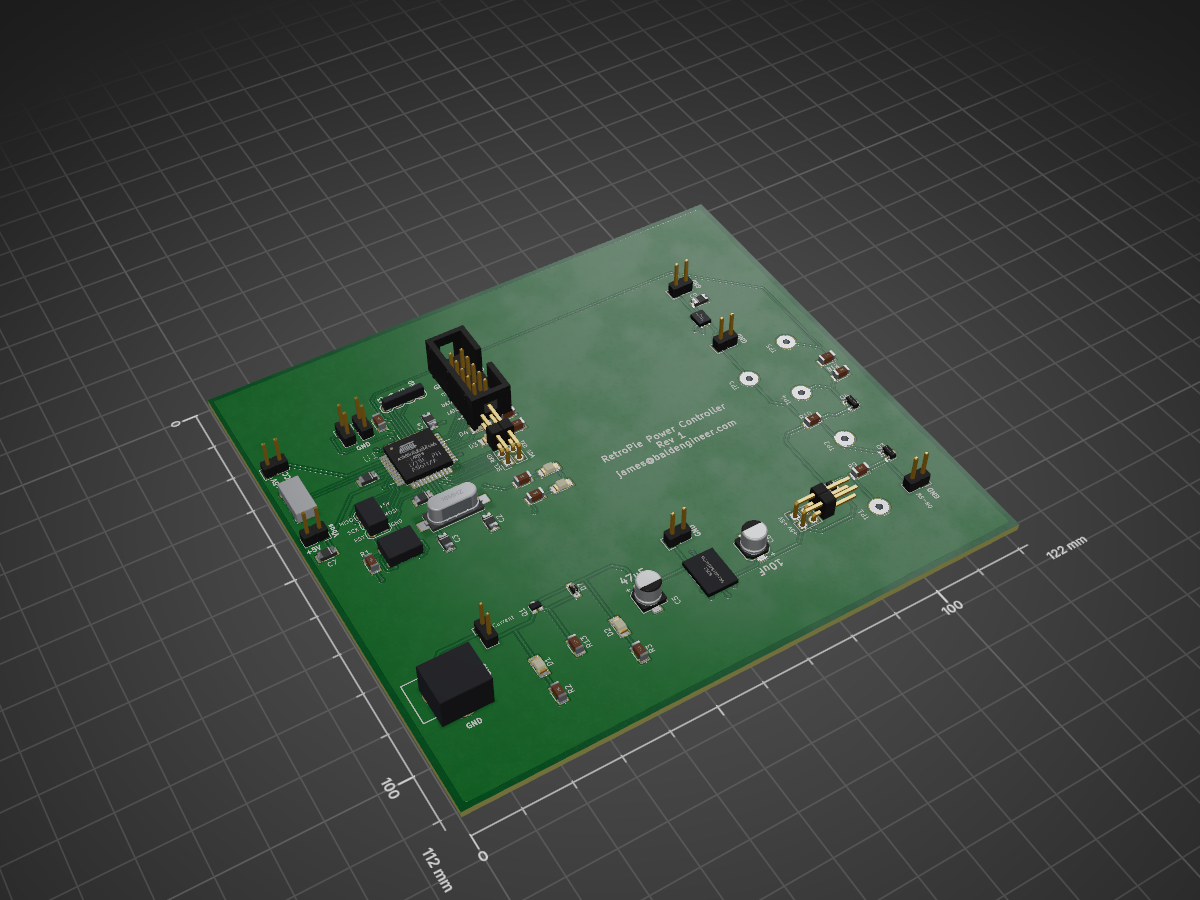
 baldengineer/Raspberry-Pi-Soft-Power-Controller21
Originally intended to be a controller for a RetroPie. A soft power controller that allows for Raspberry Pi proper shutdown. Intention is to turn this into a "hat." This is a work in progress. It works for me, kinda.
RetroPie Power Board v1a is an open-source printed circuit board by baldengineer, from the baldengineer/Raspberry-Pi-Soft-Power-Controller repository on GitHub. It is a 2-layer board of 122 × 112 mm with 59 parts on 57 nets, routed with 333 tracks and 23 vias.
It is built around the ATMEGA32U4-AU and TPS22918DBV. Its parts include 16 connectors, 13 resistors, 9 capacitors, 7 diodes and 4 transistors. It belongs with the AVR (ATmega, ATtiny) boards of this library.


For now, you can find more information at: https://hackaday.io/project/21625-raspberry-pi-soft-power-controller
| Qty | Value | Footprint | References |
|---|---|---|---|
| 9 | 1k | Resistors_SMD:R_1206 | R2, R3, R4, R5, R6, R7, R8, R12, R13 |
| 4 | 100k | Resistors_SMD:R_1206 | R1, R9, R10, R11 |
| 3 | 0.1u | Capacitors_SMD:C_1206 | C1, C4, C8 |
| 2 | 22p | Capacitors_SMD:C_1206 | C2, C3 |
| 1 | 10uF | Capacitors_SMD:C_1206 | C7 |
| 1 | 16MHz | freetronics_footprints:CRYSTAL_HC49_SMD | Y1 |
| 1 | 1nF | Capacitors_SMD:C_1206 | C9 |
| 1 | 32u4-LED1 | LEDs:LED-1206 | D3 |
| 1 | 32u4-LED2 | LEDs:LED-1206 | D4 |
| 1 | 5V-HDR | Pin_Headers:Pin_Header_Straight_2x02 | P5 |
| 1 | ATMEGA32U4-AU | ATMEGA32U4-AU:QFP80P1200X1200X120-44N | U1 |
| 1 | CAP 10uF Polymer 16V | Capacitors_SMD:c_elec_5x5.3 | C6 |
| 1 | CAP 47uF Polymer 10V | Capacitors_SMD:c_elec_5x5.3 | C5 |
| 1 | CURRENT | Pin_Headers:Pin_Header_Straight_1x02 | P1 |
| 1 | DC-In | freetronics_footprints:POWER_JACK_PTH | CON1 |
| 1 | D_Zener | Diodes_SMD:SOD-323_HandSoldering | D7 |
| 1 | EXT-HDR | freetronics_footprints:1X04 | J1 |
| 1 | FET-HDR | Pin_Headers:Pin_Header_Straight_1x02 | P13 |
| 1 | FET-Pass | TO_SOT_Packages_SMD:SOT-323 | Q2 |
| 1 | FET-Reverse | TO_SOT_Packages_SMD:SOT-323 | Q1 |
| 1 | GRN-PWRGD | LEDs:LED-1206 | D2 |
| 1 | HBEAT | Pin_Headers:Pin_Header_Straight_1x02 | P8 |
| 1 | ISP-32u4 | freetronics_footprints:2X03 | CON2 |
| 1 | LED-Front | Pin_Headers:Pin_Header_Straight_1x02 | P9 |
| 1 | Latch-B | Wire_Pads:SolderWirePad_single_1-5mmDrill | TP2 |
| 1 | Latch-NPN | TO_SOT_Packages_SMD:SOT-23 | Q3 |
| 1 | Load | Wire_Pads:SolderWirePad_single_1-5mmDrill | TP3 |
| 1 | Load | Pin_Headers:Pin_Header_Straight_1x02 | P10 |
| 1 | NCP1117ST50T3G | freetronics_footprints:SOT223 | U2 |
| 1 | ON-HDR | Pin_Headers:Pin_Header_Straight_1x02 | P7 |
| 1 | Off-Sig | Wire_Pads:SolderWirePad_single_1-5mmDrill | TP5 |
| 1 | Pass-G | Wire_Pads:SolderWirePad_single_1-5mmDrill | TP1 |
| 1 | RESET | freetronics_footprints:SW_PUSHBUTTON_SMD | SW1 |
| 1 | REV-RED | LEDs:LED-1206 | D1 |
| 1 | RXLED | LEDs:LED-1206 | D5 |
| 1 | Reset-B | Wire_Pads:SolderWirePad_single_1-5mmDrill | TP4 |
| 1 | Reset-NPN | TO_SOT_Packages_SMD:SOT-23 | Q4 |
| 1 | SER-HDR | Pin_Headers:Pin_Header_Straight_2x02 | P3 |
| 1 | SNES-HDR | Pin_Headers:Pin_Header_Straight_2x05 | P6 |
| 1 | TXLED | LEDs:LED-1206 | D6 |
| 1 | USB_5PIN_SHELL | freetronics_footprints:USB-MICRO-5pin_PTHMOUNT | P4 |
| 1 | UVCC | Pin_Headers:Pin_Header_Straight_1x02 | P12 |
| 1 | VIN-HDR | Pin_Headers:Pin_Header_Straight_1x02 | P2 |
| 1 | Vbus | Pin_Headers:Pin_Header_Straight_1x02 | P11 |
| 1 | tps22918 | freetronics_footprints:SOT23-6 | U3 |
It measures 122 × 112 mm and has 2 copper layers, 1.6 mm thick.
59 parts, built around the ATMEGA32U4-AU and TPS22918DBV. The full list of its parts is on this page, with links to each part's symbol and footprint where PCBKit's library has them.
From the baldengineer/Raspberry-Pi-Soft-Power-Controller repository on GitHub, at the commit this page was made from: the board is kicad/RetroPie Power Board/Version 1/RetroPie Power Board v1a.kicad_pcb. PCBKit opens the board in the browser, with nothing to install.
Its repository states no licence, so its author keeps all rights: ask baldengineer before reusing the design.
axiometa/BrodBoost-C2
USB - C Breadboard Powersupply: BrodBoost-C


conol-ai/openwalkietalkie
OpenMicroDial firmware — Rust/embassy on SiFli SF32LB52 (LilyGo T-Display SF32 dev board)


WsprryPi/WsprryPi-PCB-Designs
HAT and LPF Designs for the WsprryPi Organization

8aChristian/-Super-Mikrobus-Cape-Testbed
The Super Mikrobus Cape & Testbed is an industrial-grade expansion and validation platform engineered for the BeagleBone embedded computer ecosystem (BeagleBone Black, BeagleBone AI-64, BeagleY-AI, and PocketBeagle 2).

azais-corentin/espion
Multi-camera IR marker tracking: ESP32-P4/C5 firmware, Rust host, KiCad hardware