Skip to the content
2 layers61 × 63.5 mmGps, the printed circuit board in 3D

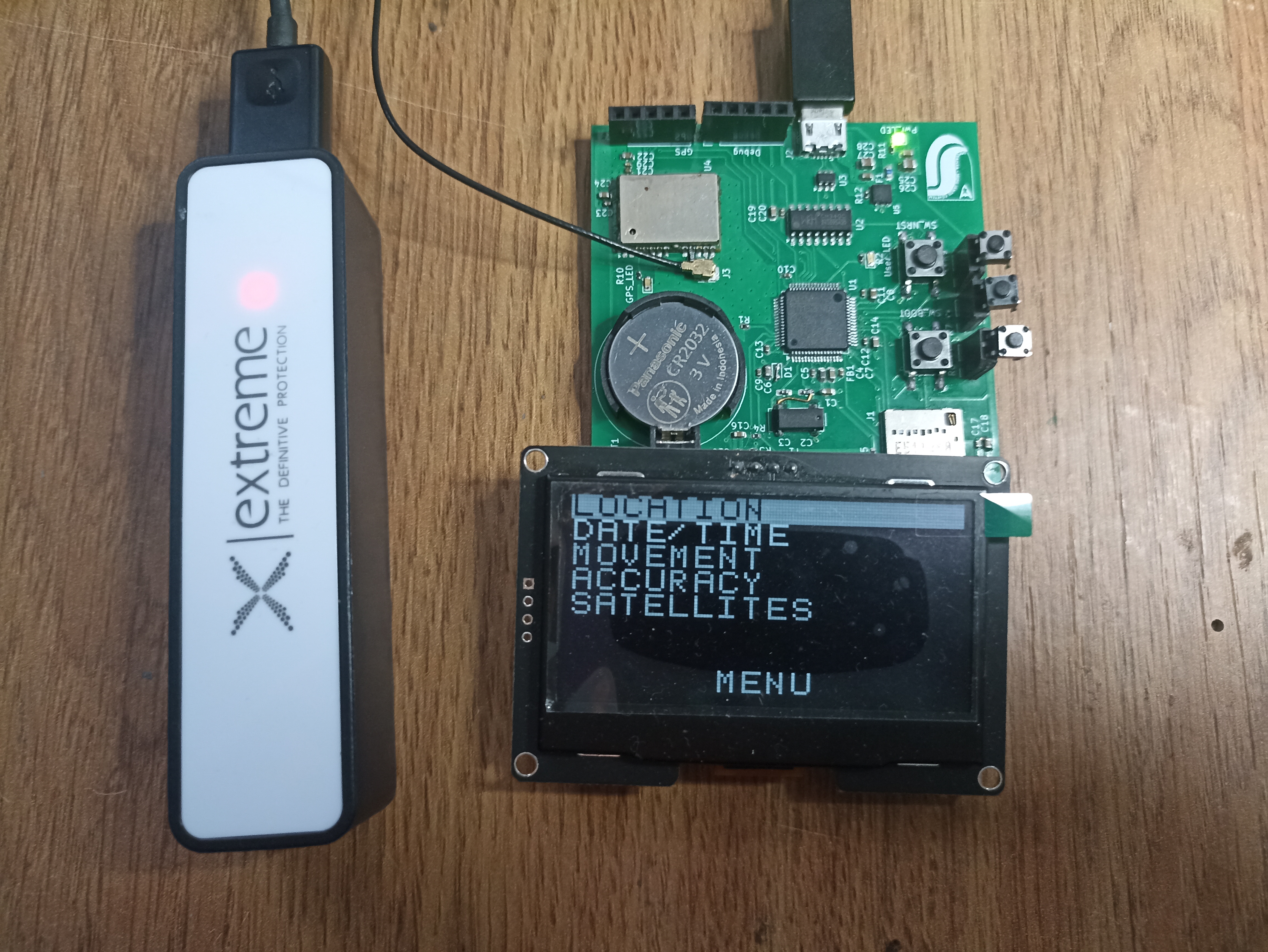
Hardware for a custom GPS system developed as part of a master’s thesis. Designed to run with the companion firmware (see gps-firmware repository).

Size
61 × 63.5 mm
Copper layers
2
Thickness
1.6 mm
Parts
66
Nets
97
Pads
279
Tracks, vias
521, 219
Pours
11
Routed
Yes
KiCad
KiCad 9.99 (file 20250401)
Created
31 Mar 2026
Updated
31 Mar 2026

Overview

Gps is an open-source printed circuit board by Baksi675, from the Baksi675/gps-hardware repository on GitHub. It is a 2-layer board of 61 × 63.5 mm with 66 parts on 97 nets, routed with 521 tracks and 219 vias.

It is built around the CH340C, LD39050PU33R and USBLC6-2SC6. Its parts include 29 capacitors, 12 resistors, 5 ICs, 3 connectors and 1 diode. It belongs with the radio and wireless boards and the STM32 boards of this library.

Main components

3

README

README.md

GPS Tracking Device — Hardware

An electronic device built for GPS tracking. The project was made with KiCad.

For the firmware repository visit gps-firmware: https://github.com/Baksi675/gps-firmware


Features

  • STM32F401RE microcontroller.
  • 32.768 kHz crystal oscillator for the internal RTC of the microcontroller.
  • USB micro B connector to power the board and to provide USB based host - target runtime communication.
  • USBLC6-2SC6 ESD protection diode network to protect the USB connector from ESD events.
  • CH340C USB-UART converter IC to provide communication capabilities between host and target with a USB cable.
  • LD30950PU33R LDO for 5 V to 3.3 V conversion.
  • u-blox NEO-6M GPS module connected to the microcontroller via UART.
  • U.FL antenna connector for the ceramic patch antenna.
  • 3 V CR2032 coin cell for the internal RTC of the microcontroller.
  • microSD card slot connected to the microcontroller via SPI.
  • Three user button connectors.
  • A 4 pin connector for the display (I2C).
  • A 5 pin debug connector (SWD).
  • A connector for an external GPS module in case the on-board module is not operational (UART).

Demonstration playlist

https://www.youtube.com/watch?v=A6QJqgy0O1o&list=PLb_bXLsinHOQtkZ2X2QlIw-E_5eapHqGd


GPS board

Parts

66
QtyValueFootprintReferences
11100nCapacitor_SMD:C_0402_1005MetricC5, C9, C10, C11, C12, C13, C15, C17, C20, C21, C23
710uCapacitor_SMD:C_0603_1608MetricC6, C14, C16, C18, C19, C22, C24
410kResistor_SMD:R_0402_1005MetricR1, R7, R8, R9
41uCapacitor_SMD:C_0603_1608MetricC1, C4, C25, C27
3220RResistor_SMD:R_0402_1005MetricR2, R10, R11
3Conn_01x02_SocketConnector_PinSocket_2.54mm:PinSocket_1x02_P2.54mm_VerticalSW_Down1, SW_Set1, SW_Up1
222uCapacitor_SMD:C_0805_2012MetricC26, C28
23k3Resistor_SMD:R_0402_1005MetricR3, R4
250kResistor_SMD:R_0402_1005MetricR5, R6
2GreenLED_SMD:LED_0603_1608MetricPower_LED1, User_LED1
2SW_PushButton_Switch_SMD:SW_Push_1P1T_NO_E-Switch_TL3301NxxxxxGSW_BOOT1, SW_NRST1
1100kResistor_SMD:R_0402_1005MetricR12
110nCapacitor_SMD:C_0402_1005MetricC7
1120RInductor_SMD:L_0603_1608MetricFB1
115pCapacitor_SMD:C_0603_1608MetricC2
115uCapacitor_SMD:C_0603_1608MetricC3
11nCapacitor_SMD:C_0402_1005MetricC29
13 VBattery:BatteryHolder_MYOUNG_BS-07-A1BJ001_CR2032BT1
132.768kHzCrystal:Crystal_SMD_SeikoEpson_MC306-4Pin_8.0x3.2mmY1
14.7uCapacitor_SMD:C_0603_1608MetricC8
1500 mAFuse:Fuse_0603_1608MetricF1
1CH340CPackage_SO:SOIC-16_3.9x9.9mm_P1.27mmU2
1Conn_01x04_PinConnector_PinHeader_2.54mm:PinHeader_1x04_P2.54mm_VerticalConn_Display1
1Conn_01x05_PinConnector_PinHeader_2.54mm:PinHeader_1x05_P2.54mm_VerticalConn_Debug1
1Conn_01x05_SocketConnector_PinSocket_2.54mm:PinSocket_1x05_P2.54mm_VerticalConn_GPS1
1Conn_CoaxialConnector_Coaxial:U.FL_Hirose_U.FL-R-SMT-1_VerticalJ3
1D_SchottkyDiode_SMD:D_0603_1608MetricD1
1LD39050PU33RCustom:LD39050PU33RU5
1LOGOLOGOG***
1Micro_SD_CardConnector_Card:microSD_HC_Molex_104031-0811J1
1NEO-6RF_GPS:ublox_NEOU4
1RedLED_SMD:LED_0603_1608MetricGPS_LED1
1STM32F401RETxPackage_QFP:LQFP-64_10x10mm_P0.5mmU1
1USBLC6-2SC6Package_TO_SOT_SMD:SOT-23-6U3
1USB_B_MicroConnector_USB:USB_Micro-B_Amphenol_10118194-0001LF_HorizontalJ2

Similar boards

  • 4 layers80 × 55 mmPicknplacepcbV3, the printed circuit board in 3D

    PicknplacepcbV3

    caleboblepias/precision-gantry-control-system

    This project implements the embedded control backbone of an automated pick and place operations. The system centers on a custom STM32F103RB-based PCB running bare-metal firmware for precise motion control of stepper and…

    52 partsMIT
  • 4 layers350 × 155 mmVentilator, the printed circuit board in 3D

    Ventilator

    RespiraWorks/Ventilator

    Fully-featured ICU ventilator design, optimized for manufacture using commonly available components and free to license.

    788 parts169Apache-2.0
  • 2 layers100 × 65 mmAstroplant AL, the printed circuit board in 3D

    Astroplant AL

    AstroPlant/astroplant-hardware

    Raw data files for hardware PCB's

    102 parts3
  • 2 layers288.1 × 97.6 mmSimplekeyboard, the printed circuit board in 3D

    Simplekeyboard

    agrantushinsky/simplekeyboard

    164 partsMIT
  • 6 layers14.5 × 90 mmNew stm32u3-203f, the printed circuit board in 3D

    New stm32u3-203f

    IsaacNorris/new-stm32u3-203f-hardware

    hardware design for my stm32 board

    82 parts
  • 4 layers36 × 60 mmSignal generator, the printed circuit board in 3D

    Signal generator

    NidasioAlberto/signal-generator

    Signal Generator with an STM32

    70 parts3
  • 2 layers81.4 × 54.9 mmEeg, the printed circuit board in 3D

    Eeg

    unaldevelopment/8-Channel-Wireless-EEG

    Bu sürümde (V2.0) tespit edilen kritik şema ve PCB tasarım hataları düzeltilmiştir: 1. STM32F446RE Besleme Kısa Devresi Giderildi: Pin 12 (VSSA) ve Pin 63 (VSS) pinlerinin +3.3V'a olan bağlantısı kesilerek GND…

    225 parts3MIT

Questions

How big is the Gps PCB?

It measures 61 × 63.5 mm and has 2 copper layers, 1.6 mm thick.

What parts does the Gps use?

66 parts, built around the CH340C, LD39050PU33R and USBLC6-2SC6. The full list of its parts is on this page, with links to each part's symbol and footprint where PCBKit's library has them.

Where can I download the Gps KiCad files?

From the Baksi675/gps-hardware repository on GitHub, at the commit this page was made from: the board is gps.kicad_pcb and its schematic USB.kicad_sch. PCBKit opens the board in the browser, with nothing to install.

Can I use the Gps design in my own project?

Its repository states no licence, so its author keeps all rights: ask Baksi675 before reusing the design.