
2 layers176 × 82.6 mm

 b3nn/3DVisionAVR-Hardware7
Hardware design files and info for 3DVisionAVR, a clone for 3D Vision Emitter using IR
Ir emit v1 is an open-source printed circuit board by b3nn, from the b3nn/3DVisionAVR-Hardware repository on GitHub, published under the MIT licence. It is a 2-layer board of 25.4 × 50.8 mm with 13 parts on 28 nets, routed with 38 tracks and 0 vias.
It is built around the IRF740. Its parts include 1 resistor and 1 diode. It belongs with the AVR (ATmega, ATtiny) boards of this library.
Hardware design files and info for 3DVisionAVR, a clone for 3D Vision Emitter using IR. This is a hardware implementation to use with Lukis101's 3DVisionAVR code
This is at an early stage and may change significantly. It should not be considered a replacement for the official 3D Vision Emitter pyramid. You will likely notice limited range of the IR signal and sync issues. Consider this a work in progress which you can help test and improve
This was designed in Kicad v6 and uses g200kg's kicad-lib-arduino library for the Sparkfun Pro Micro
The main component is an Arduino Pro Micro. This should work fine with a clone version to save a few dollars. However, to make things easy, all items can be purchased via the Sparkfun Wishlist 167547 for around $50 USD.
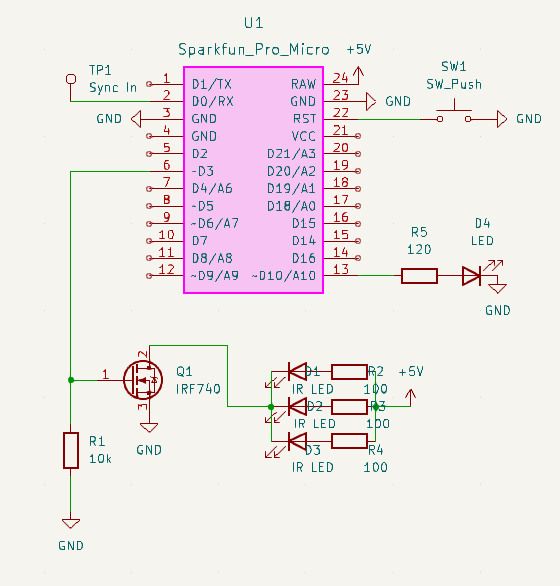
The circuit is easy to create on a breadboard.
Hook up GND on both sides of the Pro Micro to the negative rail. The mosfet source pin goes to GND and the middle drain pin goes to the cathode pin of the IR leds (short leg). Wire Pin 3 from the Pro Micro to the gate on the mosfet and then a pull down 10K resistor (connected to the negative rail). Each IR Led should have the anode (long leg) connected via a 100 ohm resistor to the RAW positive rail. Finally hook up the status LED to the signal on Pin 10 (it might be unlabeled but next to pin 16).
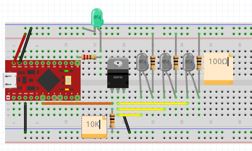
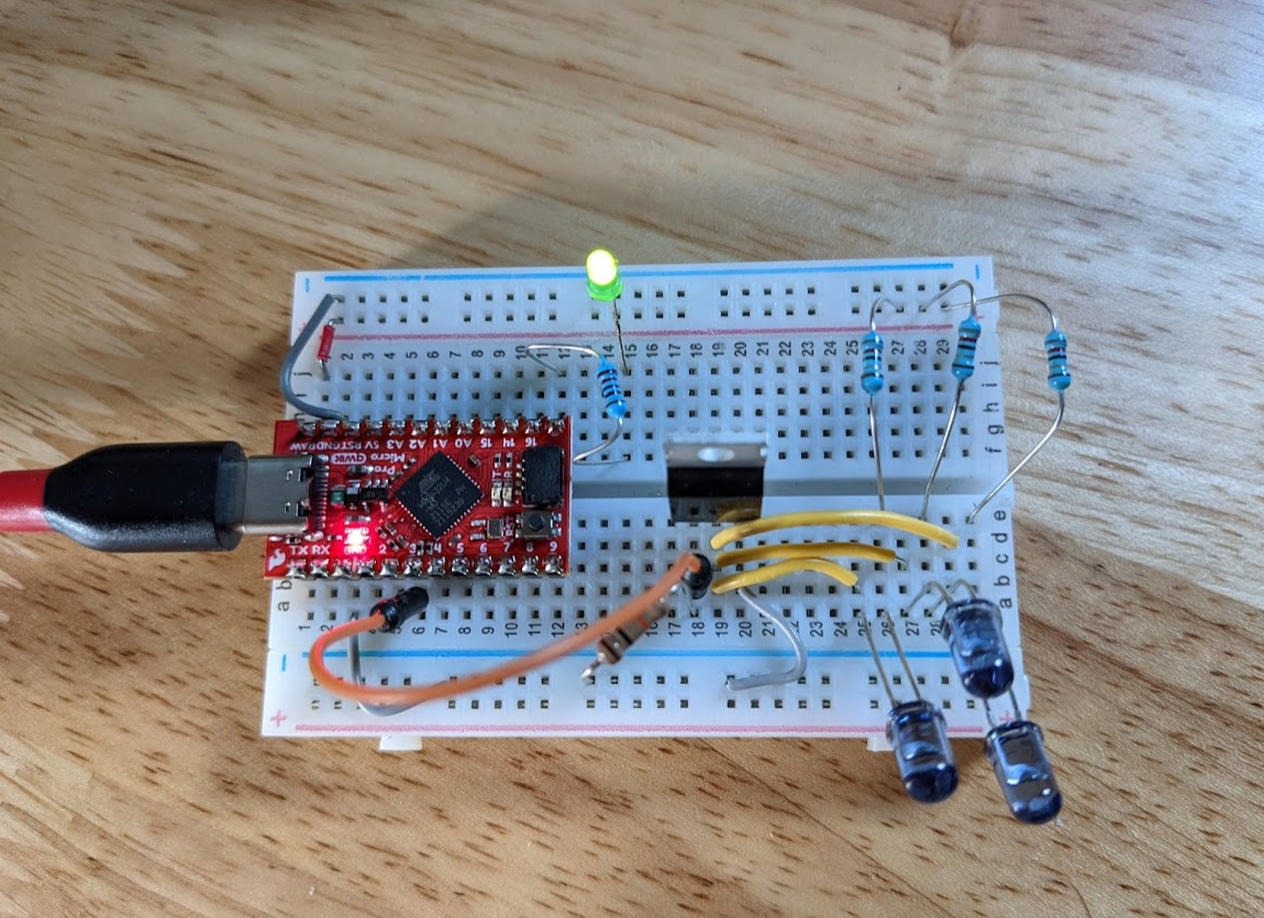
Also if you are using the VESA sync, that goes into the Pro Micro PIN 2. Point the IR LEDs at your face for best results :-)
I'm currently having this PCB fabricated, but all files are here if you would also like to fab your own. This is using common through-hole parts so it can be packaged into an easy to assemble kit.
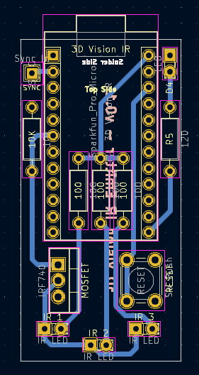
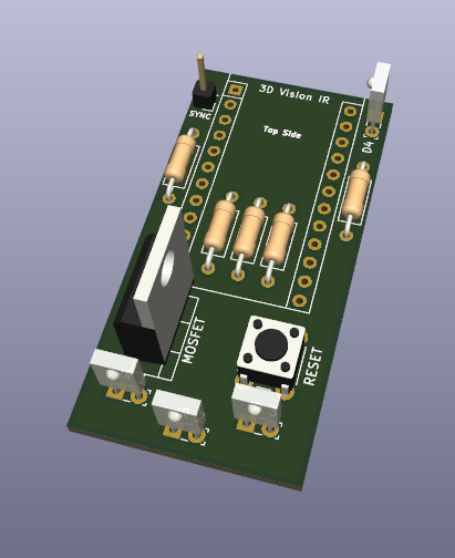
For steps on compiling and flashing Lukis101's 3DVisionAVR code for this project, view README-FLASH-FIRMWARE.md
| Qty | Value | Footprint | References |
|---|---|---|---|
| 3 | 100 | Resistor_THT:R_Axial_DIN0207_L6.3mm_D2.5mm_P10.16mm_Horizontal | 100, 100, 100 |
| 3 | IR LED | LED_THT:LED_SideEmitter_Rectangular_W4.5mm_H1.6mm | IR 1, IR 2, IR 3 |
| 1 | 10k | Resistor_THT:R_Axial_DIN0207_L6.3mm_D2.5mm_P10.16mm_Horizontal | 10K |
| 1 | 120 | Resistor_THT:R_Axial_DIN0207_L6.3mm_D2.5mm_P10.16mm_Horizontal | R5 |
| 1 | IRF740 | Package_TO_SOT_THT:TO-220-3_Vertical | MOSFET |
| 1 | LED | LED_THT:LED_SideEmitter_Rectangular_W4.5mm_H1.6mm | D4 |
| 1 | SW_Push | Button_Switch_THT:SW_PUSH_6mm | RESET |
| 1 | Sparkfun_Pro_Micro | Arduino:Sparkfun_Pro_Micro | 3D Vision IR |
| 1 | Sync In | Connector_PinHeader_2.54mm:PinHeader_1x01_P2.54mm_Vertical | SYNC |


SonOfCheevap/PierogiNixie-PSU
A simple 12v to 150v-250v DC-DC Power supply for use with nixie tubes.

CatoLynx/LAWO-Arduino
Arduino Nano adapter board for LAWO XY5 flipdot displays


It measures 25.4 × 50.8 mm and has 2 copper layers, 1.6 mm thick.
13 parts, built around the IRF740. The full list of its parts is on this page, with links to each part's symbol and footprint where PCBKit's library has them.
From the b3nn/3DVisionAVR-Hardware repository on GitHub, at the commit this page was made from: the board is ir-emit-v1.kicad_pcb and its schematic ir-emit-v1.kicad_sch. PCBKit opens the board in the browser, with nothing to install.
Its repository publishes it under the MIT licence: you may reuse it on that licence's terms (keep the author's notice, and for a copyleft licence share your changes alike).