

4 layers75 × 56.4 mm
Esp32-c6-wroom1 board
pushtiujeniya/esp32-c6-environmental-logger
This repository contains an Environmental Sensor Station and Data Logger powered by the ESP32-C6-WROOM-1 microcontroller.
59 parts4

 b-wave/Pi_Chassis_Fan_Controller
A small PCB board to interface a 5V, 4-wire fan in a controller cabinet with a Raspberry Pi controller.
Fan controller revc is an open-source printed circuit board by b-wave, from the b-wave/Pi_Chassis_Fan_Controller repository on GitHub, published under the MIT licence. It is a 2-layer board of 27.6 × 30.3 mm with 15 parts on 8 nets, routed with 77 tracks and 106 vias.
It is built around the ESD9B3.3ST5G and SS14. Its parts include 5 diodes, 3 resistors and 3 connectors.
This describes a small board to interface a 5V, 4-wire fan in a controller cabinet with a Raspberry Pi controller. The fan I am using is a GeeekPi 40x40x10mm 4-wire Fan, Model F-0028. [https://www.amazon.com/GeeekPi-Raspberry-40x40x10mm-Adjustment-Included/dp/B0CL41RG93]
The JST SH connector on the board should be compatible with the Raspberry Pi's Fan Connector. But that connector did not exist on a PI3. You DO NOT need this board to control the processor fan, it is intended to actively ventilate an enclosed, wall mounted cabinet. Yes, it is over-designed and has extras such as a static ring ground and ESD diodes - all are probably overkill but it is cheap insurance. Yes, there are three revisions. I started with a two-wire fan, then three-wire, and finally with this 4-wire version with 100% less transistors. It mainly just converts the short JST connector into a standard screw terminal.
Although I provide a separate 2-pin input voltage connector terminal block (J3) it is intended for 5-Volts only. Its purpose is to not stress the Raspberry Pi's Power supply. Although it should be perfectly fine to run the recommended fan directly off of the +5V, since it was designed to run off of the fan connector on the newer boards.
By the way, that connector is reverse voltage protected in case you get the power leads reversed - you should not damage the Pi.
Be careful if using a 12V fan! Damage may occur to 3v3 inputs and you may fry your Pi
It may need a level shifter if it does not provide 5V or pin compatible signals (TACH and maybe the PWM) - verify pin voltages before connecting to PI. If they are open collector, the 3v3 reference on the 10k pullup should take care of that.
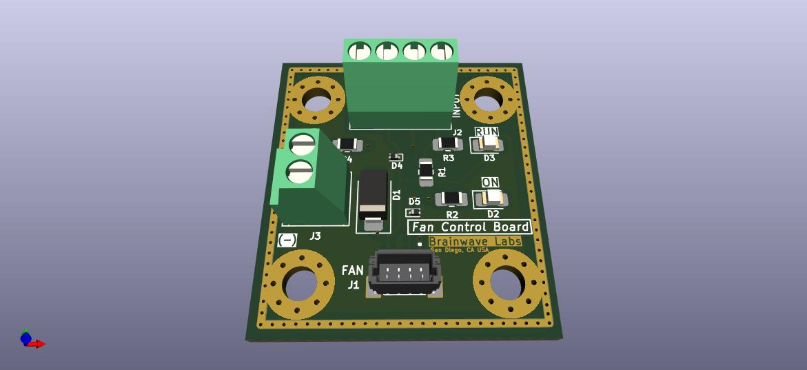
I am working on a Raspberry Pi 4 controlled LTE gateway using a small DIN rail enclosure. The planned locations are at fairly remote, and the equipment will be enclosed in a small cabinet so active ventilation is required. This board was needed to simplify installation and to provide some visual and remote feedback. This is a fairly simple board that is tailored to my specific installations, but I may expand it to be more general purpose. In any case, it provides a neat interface to control a cabinet fan I finally settled on this design:
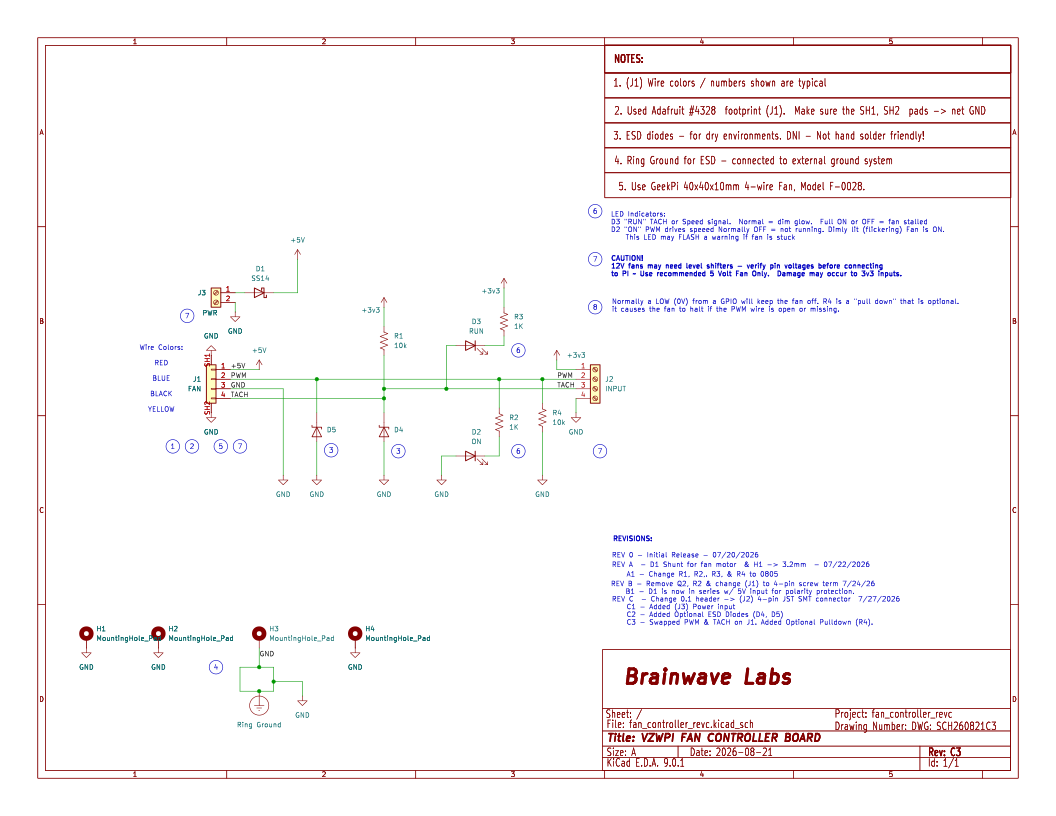
The schematic is pretty straightforward. It uses a hybrid SMT + Through-hole technologies. The ESD diodes wee exceedingly hard to hand solder so I left them off the prototype, but the rest of the board should be OK.
The hardware combines familiar building blocks with some added protection from the very warm (hot) and dry environment. I may put ESD tape and spray in my enclosure as it is intended to run in a dry dusty environment.
I am not 100% sure if the "Ring Ground" is implemented correctly. ...But it looks cool?
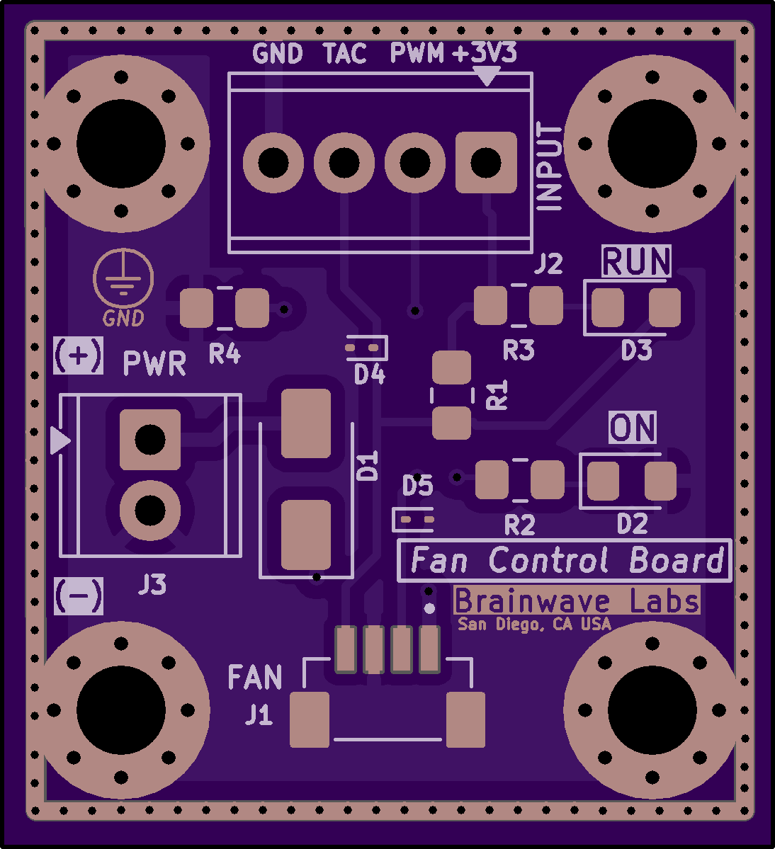
It is a approximately one inch square and is designed to fit on a small DIN rail carrier. The board is available on OSHPARK Shared and I will leave a link. www.oshpark The shown image is an early version and some components are moved. I will update and add a link after testing!
        Hole Spacing: 0.75" x 0.80" (19.0mm x 20.3mm)
        Board Outline: 1.10" x 1.20" (27.6mm x 30.2 mm)
The fan controller interface board was designed with screw blocks so you can use wires (stranded 20-22 AWG is recommend) simply strip your wire tips back ~1/8", slide them into the screw terminals, and screw to clamp them down tightly. Alternately, DuPont jumper wires should work, acting like ferrules to keep the wires from pinching. Since these connectors are on 0.1" (2.54mm) centers so you can alternately use regular pin headers and DuPont jumpers.
This connector should be compatible with most 4-wire 5V cooling fans. It helps in two ways. First you just plug in the fan, it provides an interface for the fan's connector. Secondly, since this board is meant for use in an enclosure, the fan wires usually are not long enough, so simply locate this board near the fan and run longer wires back to the Pi.
J3 pins may be used to input power for the fan. A second external power supply may be used to keep load off of the 5V Raspberry power supply. An external 5V supply should be used but it is possible to use a 12V fan but be mindful of the signals (TACH and PWM) may not have GPIO compatible levels. But typically the TACH signal is an open collector (or Drain) type so you can use the pull up and the 3v3 reference will generate the proper input signal.
J2 is the signal interface to the Raspberry PI's GPIOs needed to control and monitor the fan. Two GPIOs are needed, one output for the PWM and input for the TAC (FG) wires.
Fan 3 Volt Reference (RED) ──► Screw into terminal (3V3)
Fan PWM Control Signal (Blue) ──► Screw into terminal GPIO 12 (Pin 32)
Fan System Ground (Black) ──► Screw into terminal GND (Pin 6, 9, or 14)
Fan TACH (or FG) Speed Feedback (Yellow) ──► Screw into terminal GPIO 13 (Pin 33)
The "Fan On" or "Drive" Indicator (Green or Red)
This LED is wired to the PWM lines powering the fan. When the fan is running at full speed (100% PWM) it is ON full, when it is OFF ( 0% PWM) the fan is OFF. There is a slight dim glow green whenever the fan has power and is being driven by the PWM signal in different speeds it also changes brightness.
The "Fan Spinning" Indicator (Yellow or Blue).
This LED is wired to the TACH line to monitor it visually. Sometimes this signal is labeled Frequency Generator (FG).
When the fan is stalled or off, the LED either stays solid or completely dark. When the fan spins at high speed (e.g., 3000 RPM), the TACH pulses occur so quickly (100 times per second) that human eyes perceive the flashing as a continuous, soft glow. If the fan slows down or begins to struggle, you will visually notice the light dimming or starting to flicker. If it stops with the LED ON it will turn off after a few seconds. this is normal behavior of these fans to protect against a stall it shuts the control circuits down. It may even flash occasionally on some fans to test to see if the obstruction is clear.
Coming Soon! - no, really. Check back
| Qty | Value | Footprint | References |
|---|---|---|---|
| 3 | MountingHole | MountingHole_3.2mm_M3_DIN965 | H1, H2, H4 |
| 2 | 1K | R_0805_2012Metric_Pad1.20x1.40mm_HandSolder | R2, R3 |
| 2 | ESD9B3.3ST5G | D_SOD-923 | D4, D5 |
| 1 | 10k | R_0805_2012Metric_Pad1.20x1.40mm_HandSolder | R1 |
| 1 | FAN | ADAFRUIT_4328 | J1 |
| 1 | INPUT | TerminalBlock_Phoenix_MPT-0,5-4-2.54_1x04_P2.54mm_Horizontal | J2 |
| 1 | MountingHole_Pad | MountingHole_3.2mm_M3_Pad_Via | H3 |
| 1 | ON | LED_0805_2012Metric_Pad1.15x1.40mm_HandSolder | D2 |
| 1 | PWR | TerminalBlock_Phoenix_MPT-0,5-2-2.54_1x02_P2.54mm_Horizontal | J3 |
| 1 | RUN | LED_0805_2012Metric_Pad1.15x1.40mm_HandSolder | D3 |
| 1 | SS14 | D_SMA | D1 |
It measures 27.6 × 30.3 mm and has 2 copper layers, 1.6 mm thick.
15 parts, built around the ESD9B3.3ST5G and SS14. The full list of its parts is on this page, with links to each part's symbol and footprint where PCBKit's library has them.
From the b-wave/Pi_Chassis_Fan_Controller repository on GitHub, at the commit this page was made from: the board is hardware/fan_controller_revc.kicad_pcb and its schematic hardware/fan_controller_revc.kicad_sch. PCBKit opens the board in the browser, with nothing to install.
Its repository publishes it under the MIT licence: you may reuse it on that licence's terms (keep the author's notice, and for a copyleft licence share your changes alike).
pushtiujeniya/esp32-c6-environmental-logger
This repository contains an Environmental Sensor Station and Data Logger powered by the ESP32-C6-WROOM-1 microcontroller.

jaylingelbach/BardAssistant
A tiny “Vicious Mockery” companion built on an ESP32-S3 DevKitM-1.

Arkos-Engineering/HT-15_hardware
We can split this out into separate repos later, right now its very convenient to have everything here.

Stratolink-hq/Stratolink
An open source, upper-atmospheric, pico balloon platform.


emertcakir/OpenAirScope
Open-source air quality and environmental monitoring node with STM32H743 + ESP32-C3, LoRaWAN, RS485, USB-C, Li-ion charging, and multi-sensor support.
