ECE411
Team Members: Abdulaziz Alateeqi, Meshal Almutairi, Gene Hu, Flynn Flynn
- Size
- 1.4 × 28.9 mm
- Copper layers
- 2
- Thickness
- 1.6 mm
- Parts
- 9
- Nets
- 4
- Pads
- 91
- Tracks, vias
- 130, 4
- Pours
- 3
- Routed
- Yes
- KiCad
- KiCad 7 (file 20221018)
- Created
- 9 Oct 2023
- Updated
- 8 Dec 2023
Overview
ECE411 is an open-source printed circuit board by AzizAtk, from the AzizAtk/ECE411 repository on GitHub, published under the MIT licence. It is a 2-layer board of 1.4 × 28.9 mm with 9 parts on 4 nets, routed with 130 tracks and 4 vias.
It is built around the INMP441. Its parts include 2 ICs and 1 connector.
Main components
1README
README.mdECE411 Audio Visualizer
Team 5
Team Members: Abdulaziz Alateeqi, Meshal Almutairi, Gene Hu, Flynn Flynn
Project Overview
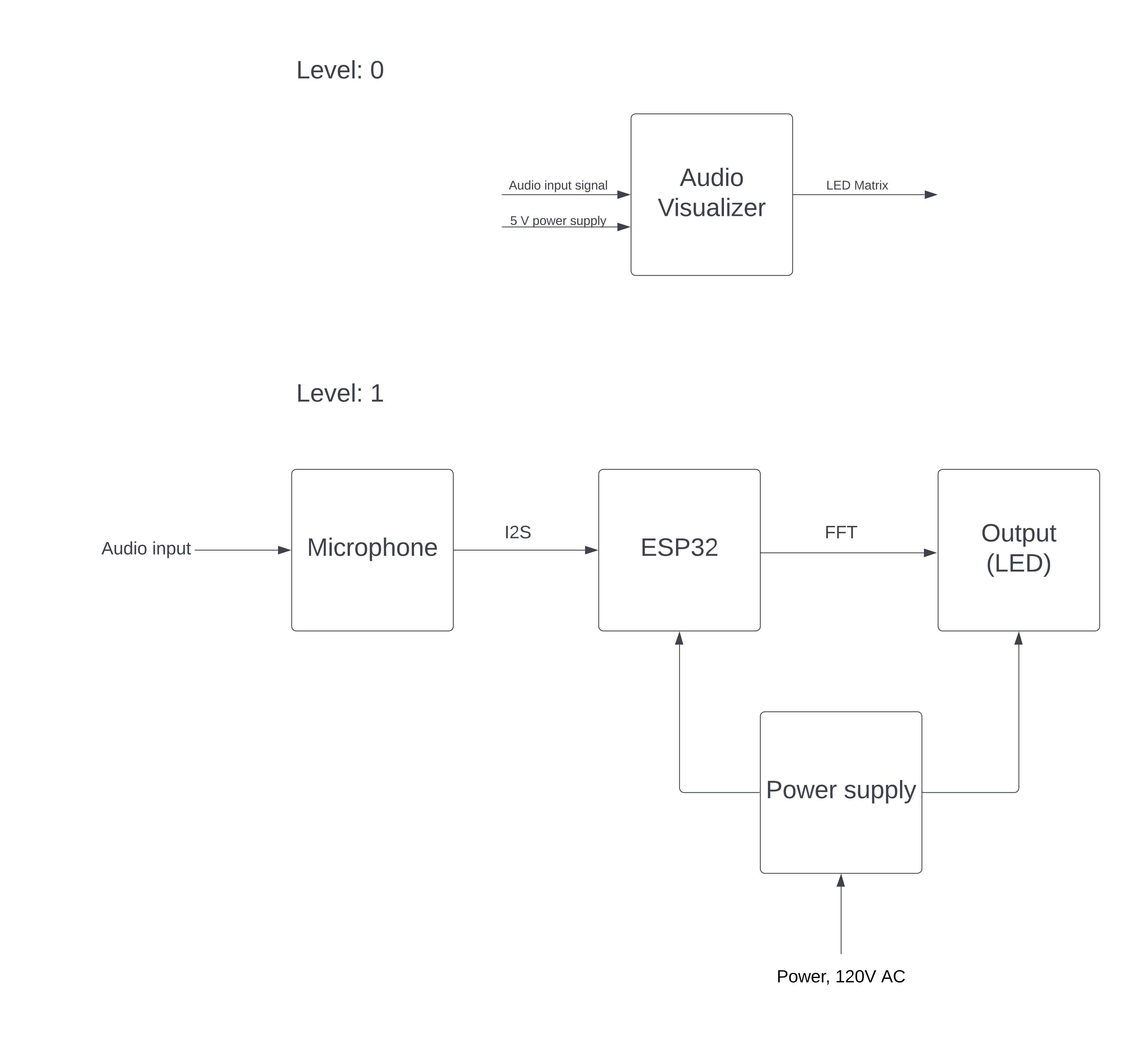
This project is a dynamic audio visualizer that reacts to the audio input signal in real-time, by illuminating an LED panel in patterns and colors corresponding to the audio’s signal. This device will be a must-have gadget for tech enthusiasts to upgrade their listening space. By utilizing digital signal processing and Fast Fourier Transforms, audio signals are displayed visually as beautiful LED arrays. Just plug the device into a standard DC USB block and turn on the power switch and the device is ready to operate.
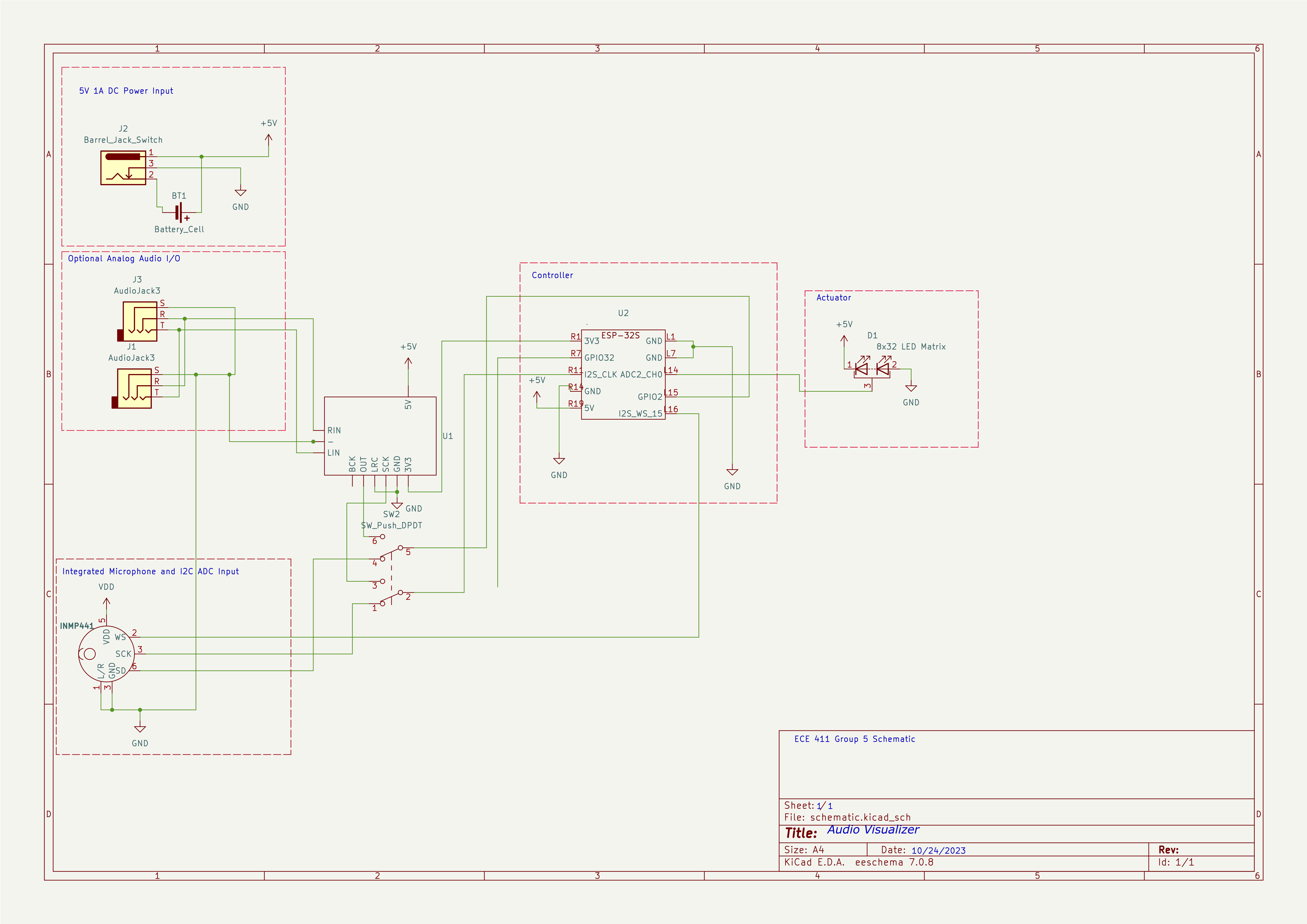
System Architecture

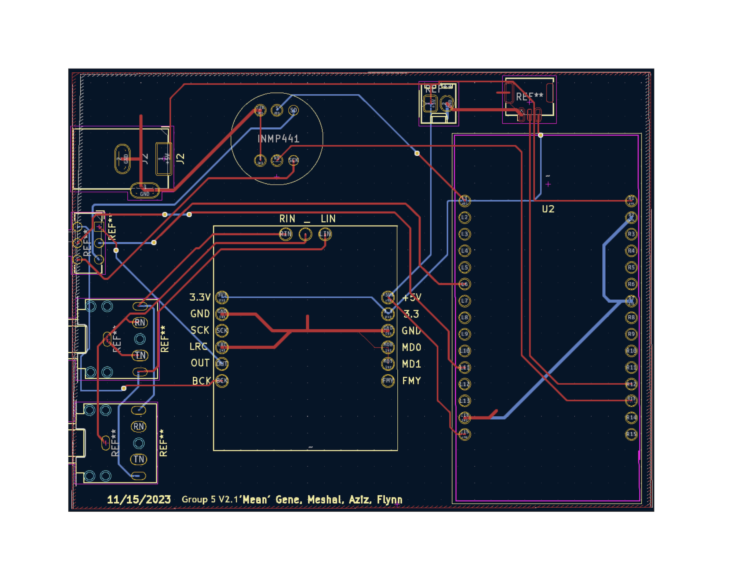
CAD Design

Software Design
Audio
- The audio is sampled using I2S.
FFT
- The FFT is implemented using the ArduinoFFT library.
- The FFT is used to convert the audio signal from the time domain to the frequency domain.
- The FFT is used to determine the amplitude of each frequency.
LED Matrix
- The LED matrix is controlled using the FastLED and LEDMatrix libraries.
- The LED matrix is used to display the amplitude of each frequency as a bar graph.
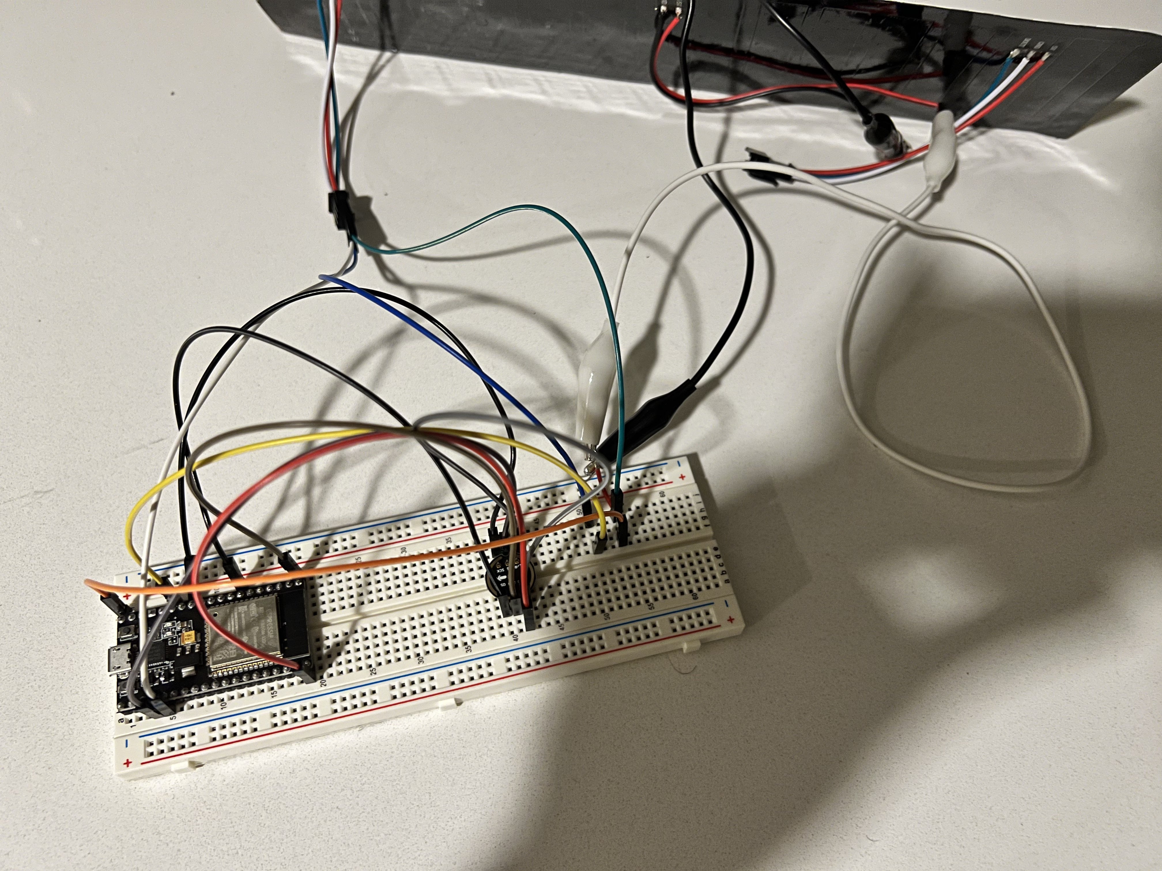
Prototype
Click to expand prototype

Design Specification
Power Requirements
The project will require dedicated 5V 3A power that will need a dedicated AC wall adapter.
- A 2.1mm barrel jack will be mounted directly to the board.
- A standard USB to 2.1mm cable will attach to a Samsung USB block.
- The 5V will attach to the board via a trace (larger duty).
Sensors
- The first input will be switchable between a 3.5mm TRS line level input.
- This will run directly to Ain and Din on the ESP32.
- The input TRS 3.5mm jack will be wired directly to a second TRS that routes audio to an external powered speaker.
- INMP441 microphone module.
- Inputs will be switchable with only one operating at a time.
Actuators
- The output of the device will be an 8x32 LED matrix.
- The display will be a two-dimensional spectrogram.
- The X-axis is the different frequencies.
- The Y-axis is amplitude in volts.
- This will be done by individually addressing each light using each frequency as a logic parameter and the voltage reading to determine how many lights from that column illuminate.
- This will be on a purchased breakout board with power, ground, and address/clk line being connected to PCB via a 4-pin ribbon cable.
Processing
- All processing will be done on an ESP32 microcontroller.
- Arduino IDE will be used as the programming environment.
- The controller will take in digital audio signals and process them into the frequency domain as a Fourier Transform.
- Different frequencies will be made into control loops for the program output.
- ESP32 will be mounted to the PCB via headers and sockets so the microcontroller can be removed for programming.
Requirements
Performance
- Must continuously visualize the input sound until switched off.
- Must be displaying accurate information (i.e., high LED bar if the frequency is overwhelming).
- Must be able to use a microphone to process the audio of surroundings.
- Should be able to take in sound through an audio jack.
- Should have a speaker.
User Experience
- Must be portable.
- Must be wall-powered through the adapter.
- Should be simple to use (plug and go).
- May use batteries.
- May be rechargeable.
Safety
- Must not overheat or be at risk of burning out LEDs.
- May be able to withstand being dropped lightly (No shattering?).
Miscellaneous
- Should be able to switch the audio rails for input/output instead of having two separate lines.
Parts
9| Qty | Value | Footprint | References |
|---|---|---|---|
| 1 | Barrel_Jack_Switch | Connector_BarrelJack:BarrelJack_GCT_DCJ200-10-A_Horizontal | J2 |
| 1 | INMP441 | footprints:INMP441 | Mic1 |
| 1 | ~ | ESP32_15x2_header:CJMCU_FT232H | U1 |
| 1 | ~ | ESP32_15x2_header:ESP32-DOIT-DEVKIT | U2 |
The 4 most common of 9 parts.
Questions
How big is the ECE411 PCB?
It measures 1.4 × 28.9 mm and has 2 copper layers, 1.6 mm thick.
What parts does the ECE411 use?
9 parts, built around the INMP441. The full list of its parts is on this page, with links to each part's symbol and footprint where PCBKit's library has them.
Where can I download the ECE411 KiCad files?
From the AzizAtk/ECE411 repository on GitHub, at the commit this page was made from: the board is KiCad/schematic.kicad_pcb and its schematic KiCad/schematic.kicad_sch. PCBKit opens the board in the browser, with nothing to install.
Can I use the ECE411 design in my own project?
Its repository publishes it under the MIT licence: you may reuse it on that licence's terms (keep the author's notice, and for a copyleft licence share your changes alike).
Similar boards
- 2 layers56.4 × 78.4 mm

- 2 layers135 × 135 mm

Va5pcb
iollama/Voice-Assistant-5
ESP32-S3 push-to-talk voice assistant using OpenAI Realtime API
16 parts21GPL-3.0 - 2 layers70 × 100 mm

Iot badge-433
galopago/iot-badge-legacy
Electronic conference badge for programming conventions, hacking events, etc.
77 parts4 - 2 layers39.1 × 39.9 mm

Nebula
Thecactusman0/Nebula-openwatch
Nebula is a ESP32 based smartwatch that features a rotating bezel encoder
85 parts4 - 2 layers74.9 × 100.3 mm

Spectrum analyzer
JadenS180/spectrum-analyzer
ESP32-based real-time audio spectrum analyzer with custom PCB design. Features INMP441 I2S microphone, SSD1306 OLED display, FFT processing, and real-time WiFi streaming to a browser-based visualizer via WebSockets.
11 parts2MIT - 2 layers33 × 77.5 mm

- 2 layers52 × 43 mm

- 2 layers80 × 50 mm

Ledhub c6
AskAlice/home-automation-pcbs
Daily Kimi-generated home automation PCB designs with KiCad sources, 3D models, and rendered documentation
59 parts1MIT