
2 layers67.5 × 14 mm
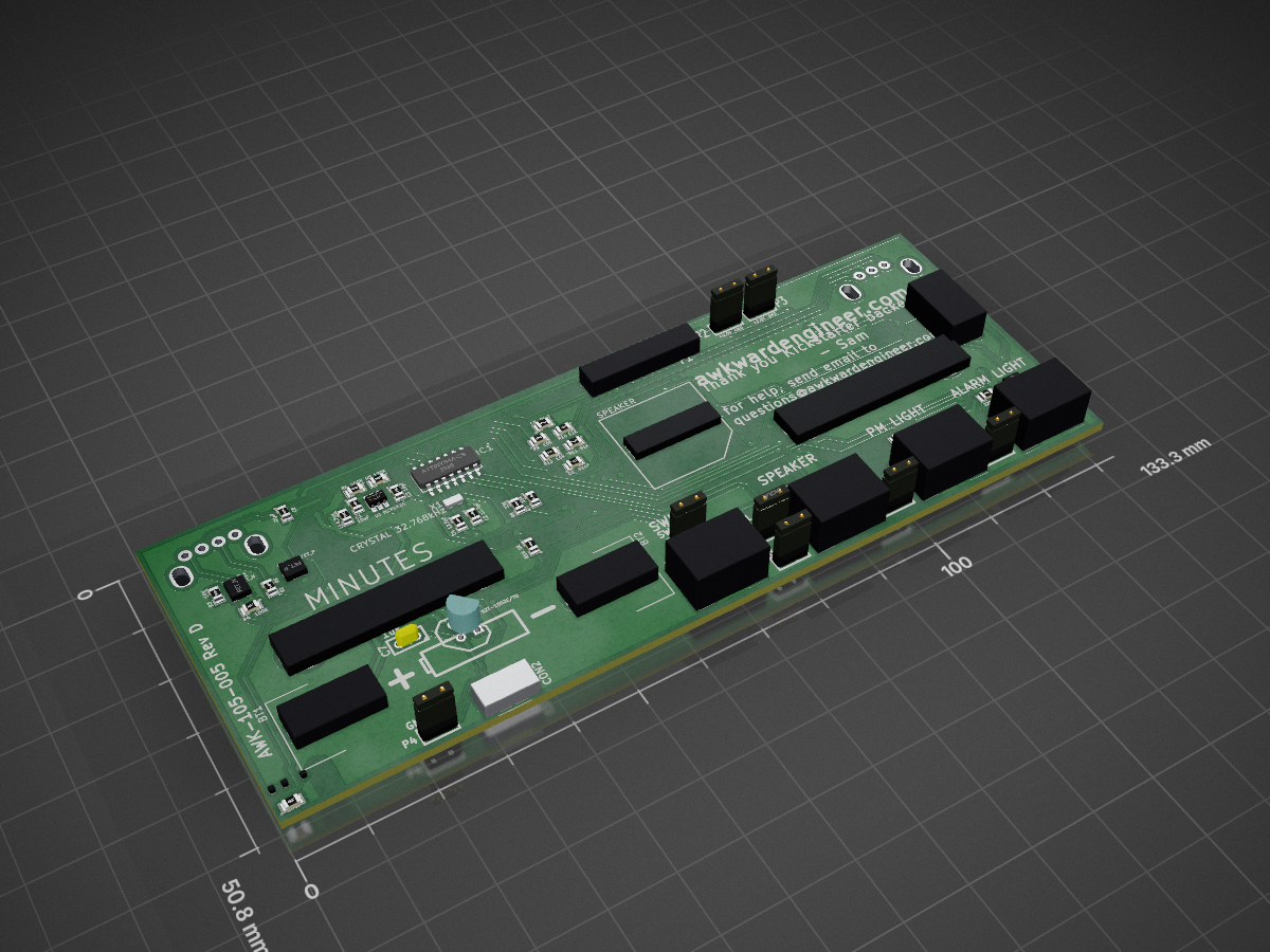
Voltmeter Clock
Clock is an open-source printed circuit board by awkwardengineer, from the awkwardengineer/Clock repository on GitHub. It is a 2-layer board of 133.4 × 50.8 mm with 62 parts on 30 nets, routed with 553 tracks and 68 vias.
It is built around the ATTINY84A-SSF and MCP1624-I/MC. Its parts include 16 resistors, 11 connectors, 10 capacitors, 5 transistors and 4 ICs. It belongs with the lEDs and displays boards and the AVR (ATmega, ATtiny) boards of this library.


This is the repository for the AWK-105 Voltmeter clock. Here is where we'll be storing requirements documents, design history files, useful tidbits of information, and other material that otherwise wouldn't be release to manufacture or included in a Bill of Materials
##Consumer Facing Page The repo may be cool, but it's not for everyone. The consumer facing product page has the bulk of the media material.
##How This Repo Is Organized In general, there are two categories of thing:
The idea was to try to organize the documentation near the design file, kindof like things are arranged below.
Clock
|
|--Mechanical
| |----CAD <=== BOM artifacts, 3d part files, drawings
| |----Design Docs <=== Documentation specific to mechanical stuff
| |----Reference Mat. <=== Usually mostly .pdfs
|
|--Electrical
| |----CAD <=== Gerbers, net files, etc...
| |----Design Docs <=== Documentation specific to electrical stuff
|
|--Photos
|
|--etc...
##Design Documents Here are some quick links to some design stuff, right off the bat.
[Requirements](Electrical/Design Docs/requirements.md)
[Microchip selection](Electrical/Design Docs/microcontroller selection.md)
Sales strategy
| Qty | Value | Footprint | References |
|---|---|---|---|
| 4 | CONN_2 | TE-connectivity-2 | P5, P6, P7, P9 |
| 4 | FET_N | SOT23 | Q1, Q3, Q4, Q5 |
| 3 | .01uF | SM0805 | C5, C6, C8 |
| 3 | 10K | SM0805 | R3, R9, R12 |
| 3 | 10uF | SM0805 | C1, C3, C9 |
| 3 | 220 | SM0805 | R13, R14, R15 |
| 3 | CONN_2 | SIL-2 | P2, P3, P4 |
| 3 | Val** | BREAK_HOLE | BREAK_TAB, BREAK_TAB, BREAK_TAB |
| 2 | 0K | SM0805 | R1, R16 |
| 2 | 12.5pF | SM0805 | C2, C4 |
| 2 | 33K | SM0805 | R7, R8 |
| 2 | 51K | SM0805 | R10, R11 |
| 2 | AMMETER | ammeter | DS1, DS2 |
| 2 | BATTERY_CLIP | AA_Battery_Clip_THRU_HOLE_BK-92 | BT1, BT2 |
| 2 | LED | SIL-2 | D2, D3 |
| 1 | 100K | bourns_knob | R2 |
| 1 | 100K | SM0805 | R4 |
| 1 | 130K | SM0805 | R5 |
| 1 | 1uF | SM0805 | C10 |
| 1 | 1uF | C1 | C7 |
| 1 | 200K | SM0805 | R6 |
| 1 | 4.7uH | SM0805 | L1 |
| 1 | ATTINY84A-SS | SO14E | IC1 |
| 1 | AVR-ISP-6 | ISPheader | CON1 |
| 1 | CONN_6 | SIL-6_s | P1 |
| 1 | CRYSTAL 32.768kHz | SMD_CRYSTAL_SMALL | X1 |
| 1 | DIODE | SM0805 | D4 |
| 1 | DIODE | SIL-2 | D1 |
| 1 | FET_P | SOT23 | Q2 |
| 1 | MCP1624 | SOT23_6 | U1 |
| 1 | MCP1702T-1502E/CB | SOT23 | U3 |
| 1 | MCP1702T-1502E/TO | TO92-INVERT | U2 |
| 1 | QUADRATURE_ENCODR | bourns_encoder | S1 |
| 1 | SPEAKER | SMT_BUZZER | SP1 |
| 1 | SPKR | SIL-2 | P8 |
| 1 | SPST | SIL-2 | SW1 |
| 1 | USB-MICRO-B | USB_MINI_B_s | CON2 |
It measures 133.4 × 50.8 mm and has 2 copper layers, 1.6 mm thick.
62 parts, built around the ATTINY84A-SSF and MCP1624-I/MC. The full list of its parts is on this page, with links to each part's symbol and footprint where PCBKit's library has them.
From the awkwardengineer/Clock repository on GitHub, at the commit this page was made from: the board is Electrical/Board Design/clock.kicad_pcb. PCBKit opens the board in the browser, with nothing to install.
Its repository states no licence, so its author keeps all rights: ask awkwardengineer before reusing the design.


mage0r/RSA0N11M9A0J_motorised_slider
This is a H-bridge driver board for the RSA0N11M9A0J motorised Slider. It uses a L9110 and capacitive sensor.


mage0r/trinkle
A breakout board for the ATTiny84. Sometimes a Trinket just won't do...

hpbock/moba-bockstelle
Ein Blockstellenmodul für analoge Modellbahnen zur Ansteuerung von Lichtsignalen, Zugbeeinflussung und Belegtmeldung für Loconet-T.


conifarad/open-lightning-trigger
A low-cost optical camera trigger for lightning and other phenomena

Dhruv2212-star/Electronic-dice
A simple device in which you press a button to get a random number between 1-6 like an actual dice but it's all inside a computer