2 layers51.5 × 104.1 mm
Analog Video Comb Filter
goscickiw/Analog-Video-Comb-Filter
Analog Composite Video to S-Video comb filter board using SAA4960, SAA4961 or SAA4963 integrated circuit
82 parts9CC-BY-SA-4.0
 avrovulcanxh607/teletext-decoder4
This repo is an attempt to open-source my teletext decoder.
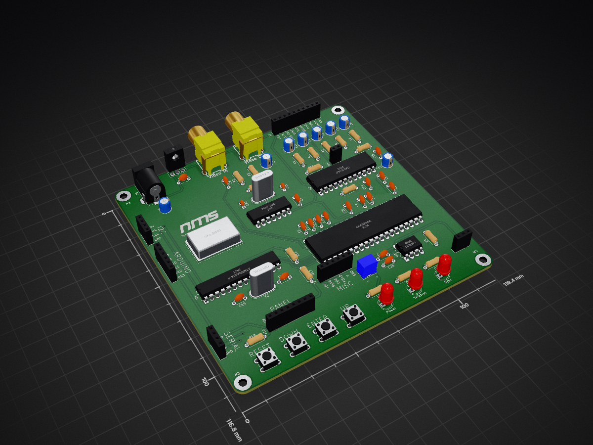
Teletext In Vision Decoder is an open-source printed circuit board by avrovulcanxh607, from the avrovulcanxh607/teletext-decoder repository on GitHub. It is a 2-layer board of 119.4 × 116.8 mm with 79 parts on 87 nets, routed with 397 tracks and 20 vias.
It is built around the ATMEGA328-PU, LM1881 and 74HCT04D, with the L7805 among its other parts. Its parts include 28 capacitors, 18 resistors, 10 connectors, 6 ICs and 4 switches. It belongs with the AVR (ATmega, ATtiny) boards of this library.


This repo is an attempt to open-source my teletext decoder.
It was originally designed, tested, and even a few were sold by me in 2019.
You can see the original product page for it on my website.
You are now free to do whatever you like with this design and the firmware for it - except selling it. You are expressly forbidden to use these designs to create a product that you then go on to resell, unless I have given you written permission otherwise.
Disclaimer: the design and firmwares are offered completely as-is, with no warranty of any kind. I will no longer be offering support or assistance on this project, if you want to build one you must figure it out from the resources provided here.
Because I have built various slightly different boards into different projects and cases for different purposes, and with different ancillaries. For example, there are code bases here which support LCD screens, IR remotes, thumbwheel selectors, serial remotes, etc. You'll probably need to try a few and modify them to suit your needs.
There are three total versions of the decoder PCB. The first version was a prototype, and features a number of mistakes - I therefore do not recommend using it. Unless you're a complete masochist.
The first revision fixes the mistakes on the prototype and is ready to use.
The second revision swaps the Arduino Nano for a standalone ATMega328(p) chip. This makes it cheaper and easier for manufacture, but harder for programming/debugging - therefore I don't recommend this revision for the novice.
Depending on how you configure the ATMega328(p) in revision 2, you may omit the crystal Y2 and associated tuning capacitors.
You may also omit R17 and R18 - these are I2C pullup resistors, and I have yet to find a need for more pullup than already onboard the microcontroller.
You need not install the output circuitry for the S-Video or RGB outputs if you don't need those - on the other hand, if you only intend to use the RGB output you can probably get rid of the entire PAL coder circuit and just bridge the chip's RGB directly to the outputs.
Really, you only actually need the teletext decoder, video input circuitry, and the microcontroller - the rest depends on what you're using it for! I have shipped some very bare boards in specific circumstances!
Similarly, the board is designed to take a 9-15v DC input and regulate it down to 5v for operation - however, the LM7805 should really have a heatsink and can be unreliable. Personally I always bridge the regulator out and supply 5v directly from an external supply.
If you are having trouble getting colour to work on the PAL CVBS or S-Video outputs, you need to check the colour subcarrier frequency. Your crystal may require slightly different tuning capacitors. However I have found most TVs to be very forgiving of the subcarrier frequency.
If you do decide to do something cool with this design, please consider posting photos of it to Bluesky and tagging "@nmsni.co.uk", I would love to see it!
Also... consider kicking a quid or two my way at Ko-Fi. It took a fair bit of time to figure this out.
| Qty | Value | Footprint | References |
|---|---|---|---|
| 15 | 100nF | Capacitor_THT:C_Disc_D4.3mm_W1.9mm_P5.00mm | C1, C2, C3, C4, C5, C6, C14, C16, C17, C20, C23, C24, C25, C27, C28 |
| 7 | 75R | Resistor_THT:R_Axial_DIN0207_L6.3mm_D2.5mm_P7.62mm_Horizontal | R2, R3, R5, R6, R7, R8, R9 |
| 6 | 220uF | Capacitor_THT:CP_Radial_D5.0mm_P2.00mm | C7, C8, C9, C10, C11, C12 |
| 4 | MountingHole_3.2mm_M3_Pad | MountingHole:MountingHole_3.2mm_M3_Pad | M3, M3, M3, M3 |
| 3 | 1k | Resistor_THT:R_Axial_DIN0207_L6.3mm_D2.5mm_P7.62mm_Horizontal | R13, R14, R15 |
| 2 | 10k | Resistor_THT:R_Axial_DIN0207_L6.3mm_D2.5mm_P7.62mm_Horizontal | R16, R17 |
| 2 | 10uF | Capacitor_THT:CP_Radial_D5.0mm_P2.00mm | C13, C15 |
| 2 | 33pF | Capacitor_THT:C_Disc_D3.0mm_W1.6mm_P2.50mm | C21, C22 |
| 2 | C | Capacitor_THT:C_Disc_D4.3mm_W1.9mm_P5.00mm | C18, C19 |
| 1 | 100nf | Capacitor_THT:C_Disc_D4.3mm_W1.9mm_P5.00mm | C26 |
| 1 | 10k | Potentiometer_THT:Potentiometer_ACP_CA6-H2,5_Horizontal | RV1 |
| 1 | 16k | Resistor_THT:R_Axial_DIN0207_L6.3mm_D2.5mm_P7.62mm_Horizontal | R10 |
| 1 | 27k | Resistor_THT:R_Axial_DIN0207_L6.3mm_D2.5mm_P7.62mm_Horizontal | R1 |
| 1 | 4.43 MHz | Crystal:Crystal_HC49-U_Vertical | Y1 |
| 1 | 4.7M | Resistor_THT:R_Axial_DIN0207_L6.3mm_D2.5mm_P7.62mm_Horizontal | R12 |
| 1 | 47k | Resistor_THT:R_Axial_DIN0207_L6.3mm_D2.5mm_P7.62mm_Horizontal | R11 |
| 1 | 680k | Resistor_THT:R_Axial_DIN0207_L6.3mm_D2.5mm_P7.62mm_Horizontal | R4 |
| 1 | 74HCT04 | Package_DIP:DIP-14_W7.62mm_LongPads | U5 |
| 1 | ARDUINO | Connector_PinSocket_2.54mm:PinSocket_1x06_P2.54mm_Vertical | J9 |
| 1 | ATmega328-P | Package_DIP:DIP-28_W7.62mm | U6 |
| 1 | CXA1645P | Package_DIP:DIP-24_W10.16mm_LongPads | U2 |
| 1 | CXO_DIP14 | Oscillator:Oscillator_DIP-14 | X1 |
| 1 | Crystal | Crystal:Crystal_HC49-U_Vertical | Y2 |
| 1 | ENTER | Button_Switch_THT:SW_PUSH_6mm | SW3 |
| 1 | I2C | Connector_PinSocket_2.54mm:PinSocket_1x04_P2.54mm_Vertical | J8 |
| 1 | IR Receiver | Connector_PinSocket_2.54mm:PinSocket_1x03_P2.54mm_Vertical | IR1 |
| 1 | L7805 | Package_TO_SOT_THT:TO-126-3_Vertical | U4 |
| 1 | LM1881 | Package_DIP:DIP-8_W7.62mm_LongPads | U3 |
| 1 | LOGO | Anything else:teletext inserter logo | G*** |
| 1 | MISC | Connector_PinSocket_2.54mm:PinSocket_1x06_P2.54mm_Vertical | J7 |
| 1 | PANEL | Connector_PinSocket_2.54mm:PinSocket_1x08_P2.54mm_Vertical | J11 |
| 1 | PDWN | Button_Switch_THT:SW_PUSH_6mm | SW2 |
| 1 | POWER | LED_THT:LED_D5.0mm | D1 |
| 1 | POWER IN | Connector_BarrelJack:BarrelJack_Horizontal | J5 |
| 1 | PUP | Button_Switch_THT:SW_PUSH_6mm | SW1 |
| 1 | R | Resistor_THT:R_Axial_DIN0207_L6.3mm_D2.5mm_P7.62mm_Horizontal | R18 |
| 1 | SAA5244A | Package_DIP:DIP-40_W15.24mm_LongPads | U1 |
| 1 | SERIAL | Connector_PinSocket_2.54mm:PinSocket_1x04_P2.54mm_Vertical | J6 |
| 1 | SW_Push | Button_Switch_THT:SW_PUSH_6mm | SW4 |
| 1 | SYNC | LED_THT:LED_D5.0mm | D2 |
| 1 | TEXT | LED_THT:LED_D5.0mm | D3 |
| 1 | VIDEO | Connector_PinSocket_2.54mm:PinSocket_1x10_P2.54mm_Vertical | J3 |
| 1 | Video In | AV Connectors:rca_yellow | J1 |
| 1 | Video Out | AV Connectors:rca_yellow | J2 |
| 1 | Y TRAP | Connector_PinSocket_2.54mm:PinSocket_1x02_P2.54mm_Vertical | J10 |
goscickiw/Analog-Video-Comb-Filter
Analog Composite Video to S-Video comb filter board using SAA4960, SAA4961 or SAA4963 integrated circuit


telec16/modular-synth
Little side project, don't expect much updates.

davischris/OpenAC1
This work is largely based on the work of Tor-Eirik Bakke Lunde (https://github.com/tebl/RC6502-Apple-1-Replica).

dennis9819/Z8C-Homebrew-Computer
To easily develop for my Z80 homebrew system, I designed a simple assempler development environment. This packs the following tasks into one script: zmac assembly object file creation (for xmodem upload) monitor file…

peterheinrich/InternetOverSpaghetti
Transmitting IP packages over a pair of spaghetti thus demonstrating how media independent IP really is.

It measures 119.4 × 116.8 mm and has 2 copper layers, 1.6 mm thick.
79 parts, built around the ATMEGA328-PU, LM1881, 74HCT04D and L7805. The full list of its parts is on this page, with links to each part's symbol and footprint where PCBKit's library has them.
From the avrovulcanxh607/teletext-decoder repository on GitHub, at the commit this page was made from: the board is PCB Files/Teletext In-Vision Decoder.kicad_pcb and its schematic PCB Files/Teletext In-Vision Decoder.kicad_sch. PCBKit opens the board in the browser, with nothing to install.
Its repository states no licence, so its author keeps all rights: ask avrovulcanxh607 before reusing the design.