2 layers100 × 100 mm
Mist1010
UzixLS/mist1010-board
10x10cm PCB variant of MIST FPGA project for G738/G706 enclosure
273 parts43MIT
 averagejmc/HomeSecurity1
A small local home security system that:
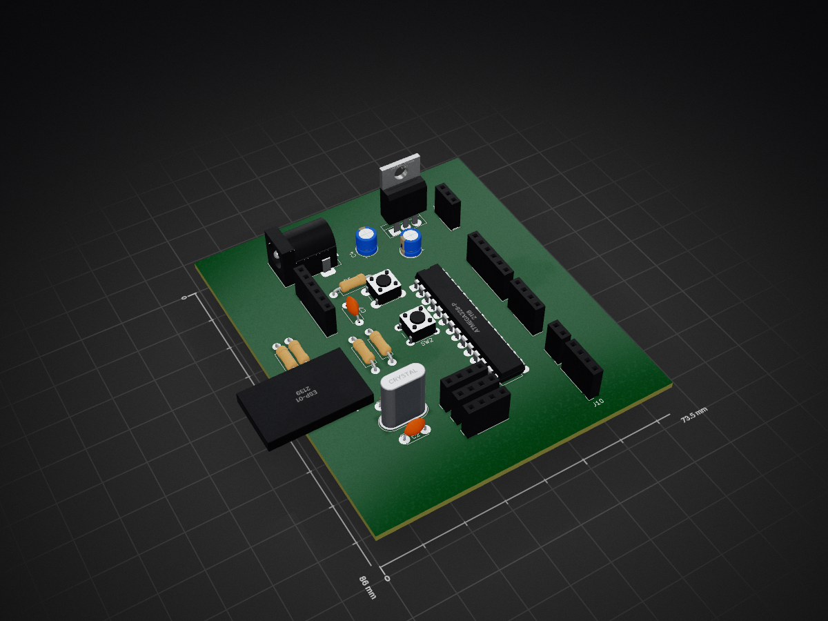
Diy arduino esp01 is an open-source printed circuit board by averagejmc, from the averagejmc/HomeSecurity repository on GitHub. It is a 2-layer board of 73.5 × 86 mm with 26 parts on 37 nets, routed with 274 tracks and 0 vias.
It is built around the ATMEGA328-PU and ESP-01. Its parts include 10 connectors, 5 capacitors, 5 resistors, 3 ICs and 2 switches. It belongs with the ESP8266 and AVR (ATmega, ATtiny) boards of this library.


A small local home security system that:
The app runs at http://localhost:5000.
localhost:1883)TELEGRAM_TOKEN=<your token>uv venv
source .venv/bin/activate # Linux/macOSWindows PowerShell:
.\.venv\Scripts\Activate.ps1uv syncFor this project, we included the bot token in the code. However, it is recommended to use environment variables instead for API and bot tokens.
Set the bot token as an environment variable:
Linux/macOS:
export TELEGRAM_TOKEN="your-token"Windows PowerShell:
setx TELEGRAM_TOKEN "your-token"mosquittouv run webapp.pyThen open:
http://localhost:5000| Qty | Value | Footprint | References |
|---|---|---|---|
| 3 | 1K | Resistor_THT:R_Axial_DIN0207_L6.3mm_D2.5mm_P10.16mm_Horizontal | R1, R2, R3 |
| 2 | 16V 1uF | Capacitor_THT:CP_Radial_D5.0mm_P2.00mm | C3, C4 |
| 2 | 22pF | Capacitor_THT:C_Disc_D5.0mm_W2.5mm_P5.00mm | C1, C2 |
| 1 | 0.1uF | Capacitor_THT:C_Disc_D5.0mm_W2.5mm_P5.00mm | C7 |
| 1 | 10K | Resistor_THT:R_Axial_DIN0207_L6.3mm_D2.5mm_P10.16mm_Horizontal | R4 |
| 1 | 3.3v | Connector_PinSocket_2.54mm:PinSocket_1x04_P2.54mm_Vertical | J10 |
| 1 | 3.3v | Connector_PinSocket_2.54mm:PinSocket_1x03_P2.54mm_Vertical | J1 |
| 1 | 500 | Resistor_THT:R_Axial_DIN0207_L6.3mm_D2.5mm_P10.16mm_Horizontal | R6 |
| 1 | 5V | Connector_PinSocket_2.54mm:PinSocket_1x04_P2.54mm_Vertical | J9 |
| 1 | ATmega328-P | Package_DIP:DIP-28_W7.62mm | U1 |
| 1 | Anaolg Pins | Connector_PinSocket_2.54mm:PinSocket_1x06_P2.54mm_Vertical | J7 |
| 1 | Barrel_Jack | Connector_BarrelJack:BarrelJack_Horizontal | J3 |
| 1 | CP0102 | Connector_PinSocket_2.54mm:PinSocket_1x06_P2.54mm_Vertical | J2 |
| 1 | Crystal | Crystal:Crystal_HC49-U_Vertical | Y1 |
| 1 | D5 | Connector_PinSocket_2.54mm:PinSocket_1x04_P2.54mm_Vertical | J4 |
| 1 | ESP-01 | ESP-01:MODULE_ESP-01 | U3 |
| 1 | LM7805_TO220 | Package_TO_SOT_THT:TO-220-3_Vertical | U2 |
| 1 | RFID | Connector_PinSocket_2.54mm:PinSocket_1x04_P2.54mm_Vertical | J5 |
| 1 | RFID | Connector_PinSocket_2.54mm:PinSocket_1x02_P2.54mm_Vertical | J8 |
| 1 | SW_Push | Button_Switch_THT:SW_PUSH_6mm | SW1 |
| 1 | gnd | Connector_PinSocket_2.54mm:PinSocket_1x04_P2.54mm_Vertical | J11 |
| 1 | hardware interupt | Button_Switch_THT:SW_PUSH_6mm | SW2 |
It measures 73.5 × 86 mm and has 2 copper layers, 1.6 mm thick.
26 parts, built around the ATMEGA328-PU and ESP-01. The full list of its parts is on this page, with links to each part's symbol and footprint where PCBKit's library has them.
From the averagejmc/HomeSecurity repository on GitHub, at the commit this page was made from: the board is schematic/diy_arduino_esp01/diy_arduino_esp01.kicad_pcb and its schematic schematic/diy_arduino_esp01/diy_arduino_esp01.kicad_sch. PCBKit opens the board in the browser, with nothing to install.
Its repository states no licence, so its author keeps all rights: ask averagejmc before reusing the design.
UzixLS/mist1010-board
10x10cm PCB variant of MIST FPGA project for G738/G706 enclosure

michar71/DMX_CTRL
DMX512 Controller for light installations based on Bluepill STM32F103 Board


Rangarig/MK312WIFI
A replacement for the MK312's bluetooth adapter that allows to connect to it via wifi ... or comport

slemanz/chronolog
STM32-based temperature data logger with RTC, NOR flash storage, LCD and Wi-Fi. Hardware and firmware.

beckdac/uArm-MicroView-esp8266
uArm control PCB with MicroView (Arduino w/ OLED) and esp8266 WiFi/UART bridge


ArtoLabs/Sensi-pot
Collection of modules for indoor/outdoor gardening automation and environmental control