2 layers245.1 × 160 mm
8-Bit CPU 32k
slu4coder/Minimal-64x4-Home-Computer
My DIY TTL home computer with VGA and PS/2 and 4x the processing power of a Commodore C64 or Apple II.
139 parts326

 ausandavno/ISA_POST_Card_v524
A plug-in diagnostic card that displays Power On Self Test (POST) codes on an 8-bit ISA data bus. Tested for use with Micro8088 and Xi8088 systems. Can be configured to listen on any address in the lower ten bits of address space.
ISA POST Card v5.1 is an open-source printed circuit board by ausandavno, from the ausandavno/ISA_POST_Card_v5 repository on GitHub. It is a 2-layer board of 108 × 64.1 mm with 40 parts on 137 nets, routed with 888 tracks and 52 vias.
It is built around the 74HCT132D, 74LS74PC and LTS-2801AG. Its parts include 10 ICs, 9 capacitors, 6 diodes, 5 resistors and 2 switches. It belongs with the FPGA and CPLD boards of this library.


Version 5.1 of a plug-in diagnostic card that displays Power On Self Test (POST) codes on an 8-bit ISA data bus. Tested for use with Micro8088 and Xi8088 systems. Can be configured to listen on any address in the lower ten bits of address space.
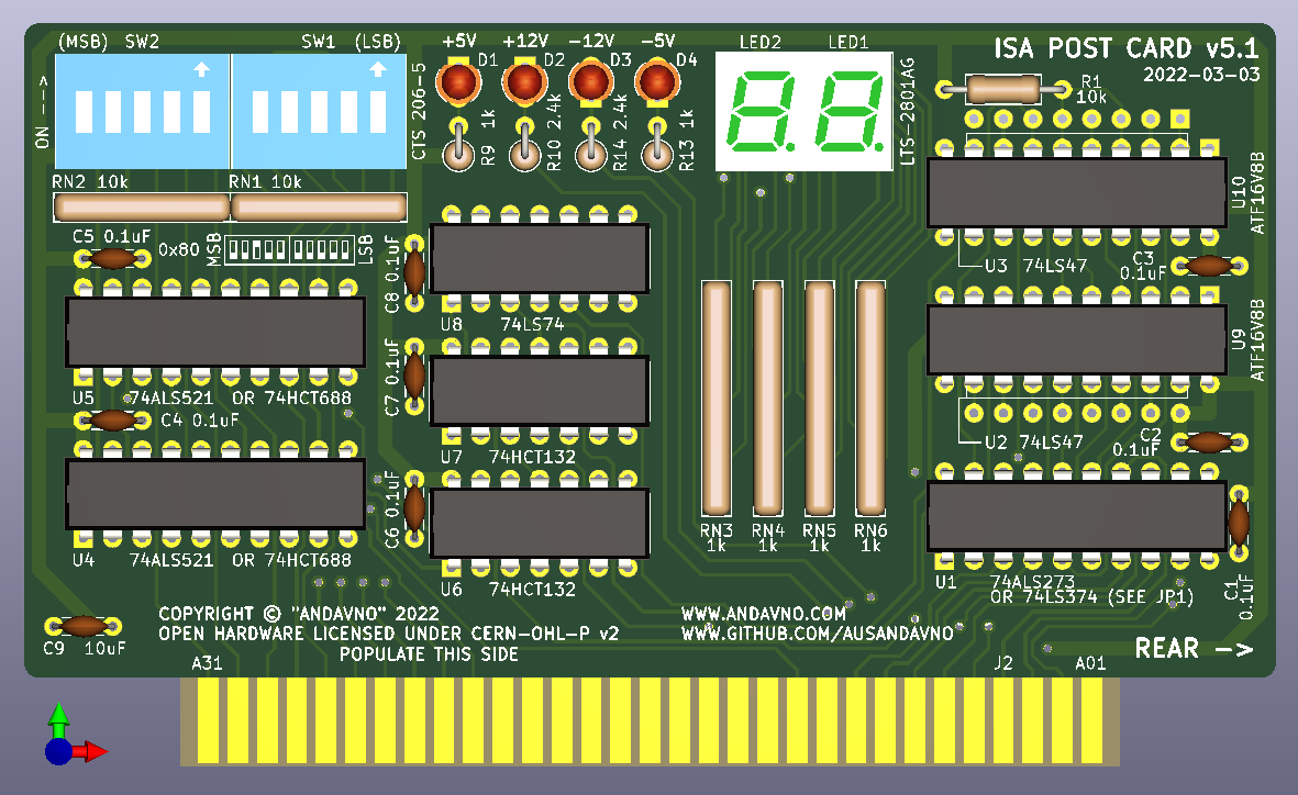
Board render:
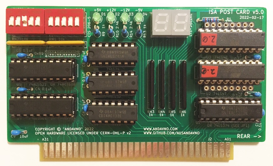
Constructed board (ignore version number):
Schematics - Version 5.1 (pdf)
PCB Layout - Version 5.1 (zip)
Recommend soldering components in order of height, lowest to highest: Resistors (Rx), IC sockets (if used), Resistor Networks (RNx), Capacitors (Cx), Discrete LEDs (Dx), Seven Segment LEDs (LEDx), Switches (SWx).
Recommend populating turned-pin strip headers for U2, U3, U9 and U10. Populate U2, U3 if intending to use seven-segment display driver 74LS47. Populate U9, U10 if intending to use ATF16V8B-15PU to display hexadecimal values.
| Position | Description |
|---|---|
| 1-2 closed (default)* | Use 74x273 Series |
| 2-3 closed | Use 74x374 Series |
*Cut trace to open 1-2
| Position | Description |
|---|---|
| SW1.1 | bit 4 of address space |
| SW1.2 | bit 3 of address space |
| SW1.3 | bit 2 of address space |
| SW1.4 | bit 1 of address space |
| SW1.5 | bit 0 of address space (LSB) |
| Position | Description |
|---|---|
| SW2.1 | bit 9 of address space (MSB) |
| SW2.2 | bit 8 of address space |
| SW2.3 | bit 7 of address space |
| SW2.4 | bit 6 of address space |
| SW2.5 | bit 5 of address space |
| Component type | Reference | Description | Quantity | Possible sources and notes |
|---|---|---|---|---|
| PCB | ISA Post Card v5.1 | 1 | Use supplied Gerber or KiCad files to order from your perferred PCB fabrication house | |
| Integrated Circuit | U1 | 74ALS273 or 74ALS374 (See JP1 Setting) | 1 | Mouser SN74ALS273N or SN74ALS374AN |
| Integrated Circuit | U2, U3 | 74LS47 (Alternative to U9, U10) | 2 | Mouser SN74LS47NE4 |
| Integrated Circuit | U4, U5 | 74ALS521 or 74HCT688 | 2 | Mouser SN74ALS521N or CD74HCT688E |
| Integrated Circuit | U6, U7 | 74HCT132 | 2 | Mouser CD74HCT132E |
| Integrated Circuit | U8 | 74LS74 | 1 | Mouser SN74LS74AN |
| Integrated Circuit | U9, U10 | ATF16V8B (Alternative to U2, U3) | 2 | Mouser ATF16V8B-15PU |
| LED | LED1, LED2 | 7-Segment Display W7.4mm H10mm | 2 | Mouser LTS-2801AG or LTS-2801AWC |
| LED | D1 - D4 | LED D3.0mm | 4 | Mouser LTL-4231N |
| Resistor Network | RN1, RN2 | R_Array_SIP6 10K (Bussed) | 2 | Mouser 4606M-101-103LF |
| Resistor Network | RN3 - RN6 | R_Array_SIP8 1K (Isolated) | 4 | Mouser L083S122LF |
| Resistor | R1 | R_Axial_DIN0207 L6.3mm D2.5mm P10.16mm 10K | 1 | Mouser MFR-25FRF52-10K |
| Resistor | R9, R13 | R_Axial_DIN0207 L6.3mm D2.5mm P10.16mm 1k | 2 | Mouser MFR-25FRF52-1K |
| Resistor | R10, R14 | R_Axial_DIN0207 L6.3mm D2.5mm P10.16mm 2.4k | 2 | Mouser MFR-25FRF52-2K4 |
| Capacitor | C1 - C8 | P5.08mm 0.1uF 50V | 8 | Mouser FG28X7R1H104KNT06 |
| Capacitor | C9 | P5.08mm 10uF 10V | 1 | Mouser FG24X7R1A106KRT06 |
| Switch | SW1, SW2 | SW_DIP_SPSTx05_Slide 9.78x14.88mm W7.62mm P2.54mm | 2 | Mouser CTS 206-5 or C&K BD05 |
| Socket | for U1, U4, U5 | 20 pin 300 mil DIP socket | 3 | Mouser 4820-3000-CP |
| Socket | for U6, U7, U8 | 14 pin 300 mil DIP socket | 3 | Mouser 4814-3000-CP |
| Socket * | for U9, U10 | 10 WAY SIL VERT SKT | 4 | Mouser D01-9971042 |
| Socket * | for U2, U3 | 8 WAY SIL VERT SKT | 4 | Mouser D01-9970842 |
| Socket ** | Alt for U9, U10 | 20 pin 300 mil DIP socket | 2 | Mouser 4820-3000-CP |
| Socket ** | Alt for U2, U3 | 16 pin 300 mil DIP socket | 2 | Mouser 4816-3000-CP |
*Recommended to use SIL Sockets instead of DIP sockets if you want to swap between fitting U2, U3 and U9, U10.
**Use DIP sockets if you are comfortable committing to either U2, U3 or U9, U10. Cannot swap between chip types without removing DIP socket.
Supply chain distruptions have caused havoc with availability of ICs. Below are some suggestions for alternative types that are likely to work as substitues to those in the BOM. NOTE: not all alternative chip types or combinations of chip types have been tested. Use caution substituting CMOS types for Bipolar types. Bipolar outputs to CMOS inputs may give issues with voltage levels.
74ALS273 Alternatives:
74ALS374 Alternatives:
74ALS521 Alternatives:
74HCT688 Alternatives:
74HCT132 Alternatives:
74LS74 Alternatives:
The ATF16V8B-15PU chip (U9, U10) can be chosen as a substitute to the 74LS47 (U2, U3). The ATF16V8B chip is primarily used to emulate a 74LS47 seven segment display decoder IC with additional/new hex-output functionality. If one would like to be able to see hexadecimal values on the seven-segment displays of the POST card, then the ATF16V8B should be chosen.
The ATF16V8B must be programmed with a ".jed" file. A copy of this file "HEX_TO_7SEG_DECODER_COM_AN_V2.0.jed" has been placed in the "ATF16V8B_JED" folder.
Refer to my Hex_To_Seven_Segment_Decoder repository for associated WinCUPL project files.
Refer to My website for an overview of recent changes to the ATF16V8B program.
For some instruction on how to compile the WinCUPL code for the ATF16V8B, please see “How to Compile the Code” section of my post 7 segment display decoder with HEX output.
For some instruction on how to go about programming the ATF16V8B with a TL866II PLUS programmer, please see “Flashing U16” section of my post on building the Micro 8088.
You may redistribute and modify this Covered Source, and make products using it, under the terms of the CERN-OHL-P v2 (https:/cern.ch/cern-ohl). This Covered Source is distributed WITHOUT ANY EXPRESS OR IMPLIED WARRANTY, INCLUDING OF MERCHANTABILITY, SATISFACTORY QUALITY AND FITNESS FOR A PARTICULAR PURPOSE. Please see the CERN-OHL-P v2 for applicable conditions.
Warranty Disclaimed per 5.1 of CERN-OHL-P v2.
Liability Excluded and Limited per 5.2 of CERN-OHL-P v2.
See "LICENSE_NOTICES_and_CHANGES.txt" for specific Notices relating to this hardware design.
| Qty | Value | Footprint | References |
|---|---|---|---|
| 8 | 0.1uF | Capacitor_THT:C_Disc_D4.3mm_W1.9mm_P5.08mm | C1, C2, C3, C4, C5, C6, C7, C8 |
| 4 | 1k | Resistor_THT:R_Array_SIP8 | RN3, RN4, RN5, RN6 |
| 4 | LED | LED_THT:LED_D3.0mm | D1, D2, D3, D4 |
| 2 | 10k | Resistor_THT:R_Array_SIP6 | RN1, RN2 |
| 2 | 1k | Resistor_THT:R_Axial_DIN0207_L6.3mm_D2.5mm_P2.54mm_Vertical | R9, R13 |
| 2 | 2.4k | Resistor_THT:R_Axial_DIN0207_L6.3mm_D2.5mm_P2.54mm_Vertical | R10, R14 |
| 2 | 74ALS521 | Package_DIP:DIP-20_W7.62mm | U4, U5 |
| 2 | 74HCT132 | Package_DIP:DIP-14_W7.62mm | U6, U7 |
| 2 | 74LS47 | Package_DIP:DIP-16_W7.62mm | U2, U3 |
| 2 | ATF16V8B | Package_DIP:DIP-20_W7.62mm | U9, U10 |
| 2 | LTS-2801AG | Display_7Segment:LTS-2801AG | LED1, LED2 |
| 2 | SW_DIP_x05 | Button_Switch_THT:SW_DIP_SPSTx05_Slide_9.78x14.88mm_W7.62mm_P2.54mm | SW1, SW2 |
| 1 | 10k | Resistor_THT:R_Axial_DIN0207_L6.3mm_D2.5mm_P10.16mm_Horizontal | R1 |
| 1 | 10uF | Capacitor_THT:C_Disc_D4.3mm_W1.9mm_P5.08mm | C9 |
| 1 | 74ALS273 | Package_DIP:DIP-20_W7.62mm | U1 |
| 1 | 74LS74 | Package_DIP:DIP-14_W7.62mm | U8 |
| 1 | Bus_ISA_8bit_AB_Rev0 | Connector_PCBEdge:ISA_CARD_EDGE_CONNECTOR_8BIT_Rev1 | J2 |
| 1 | SolderJumper_3_Bridged12 | Jumper:SolderJumper-3_P1.3mm_Bridged12_RoundedPad1.0x1.5mm_NumberLabels | JP1 |
slu4coder/Minimal-64x4-Home-Computer
My DIY TTL home computer with VGA and PS/2 and 4x the processing power of a Commodore C64 or Apple II.


slu4coder/Minimal-64-Home-Computer
Legacy: Full TTL-only home computer with VGA and PS/2 and twice the processing power of a Commodore 64


MadsRudolph/vinyl-adc
Discrete 3rd-order delta-sigma stereo audio ADC, built from op-amps and logic gates: a four-layer Raspberry Pi HAT made by PCBWay, with KiCad files, SPICE simulations and measurements


jotego/jtcores
FPGA cores compatible with multiple arcade game machines and KiCAD schematics of arcade games. Working on MiSTer FPGA/Analogue Pocket

It measures 108 × 64.1 mm and has 2 copper layers, 1.6 mm thick.
40 parts, built around the 74HCT132D, 74LS74PC and LTS-2801AG. The full list of its parts is on this page, with links to each part's symbol and footprint where PCBKit's library has them.
From the ausandavno/ISA_POST_Card_v5 repository on GitHub, at the commit this page was made from: the board is v5.1/ISA_POST_Card_v5.1.kicad_pcb. PCBKit opens the board in the browser, with nothing to install.
Its repository states no licence, so its author keeps all rights: ask ausandavno before reusing the design.