2 layers65.5 × 60.8 mm
Raspi pico christmas tree
jcksnvllxr80/raspi_pico_christmas_tree
This project was designed for a decorative Christmas tree made out of cedar which stands about two feet in height.
19 parts1

 attilabody/gate4331
Shared parking space gate controller with 433 MHz radio
Bluepill is an open-source printed circuit board by attilabody, from the attilabody/gate433 repository on GitHub. It is a 2-layer board of 50 × 100 mm with 82 parts on 64 nets, routed with 470 tracks and 19 vias.
It is built around the ESP-01, 24LC512-I/P and LM1117-3.3, with the IRLML2502 among its other parts. Its parts include 24 resistors, 19 connectors, 12 ICs, 11 capacitors and 6 diodes. It belongs with the ESP8266 boards of this library.


Gate433 uses cheap, standard (and insecure) gate opener remotes operating on 433 MHz to control entry and exit of vehicles allowed to acces the parking area.
Each gate opener supposed to be assigned to one vehicle and has unique code. The main purpose of it is to make unfair usage of the parking as inconvinient as possible using commodity gate opener remotes.
Features list:
There are two versions of the hardware: Original version used Arduino Nano as central component. It is obsoleted by the newer version based on a popular STM32F103C8T6 based minimal board widely known as BluePill. It's actually cheaper on eBay or Aliexpress than the total cost of the components it contains.
Both versions ar using two inputs (usually coming from inductive loop detectors) in addition to the RF signal to decide if a vehicke intends to enter or exit. A pair of tricolor traffic lights provide feedback for drivers.
Both versions have 6 opto-isolated open drain output for 12V LED traffic lights,one opto-isolated open collector output for gate opening and two opto-isolated input for inductive loop detectors.
Second iteration have three extra features compared to the first:
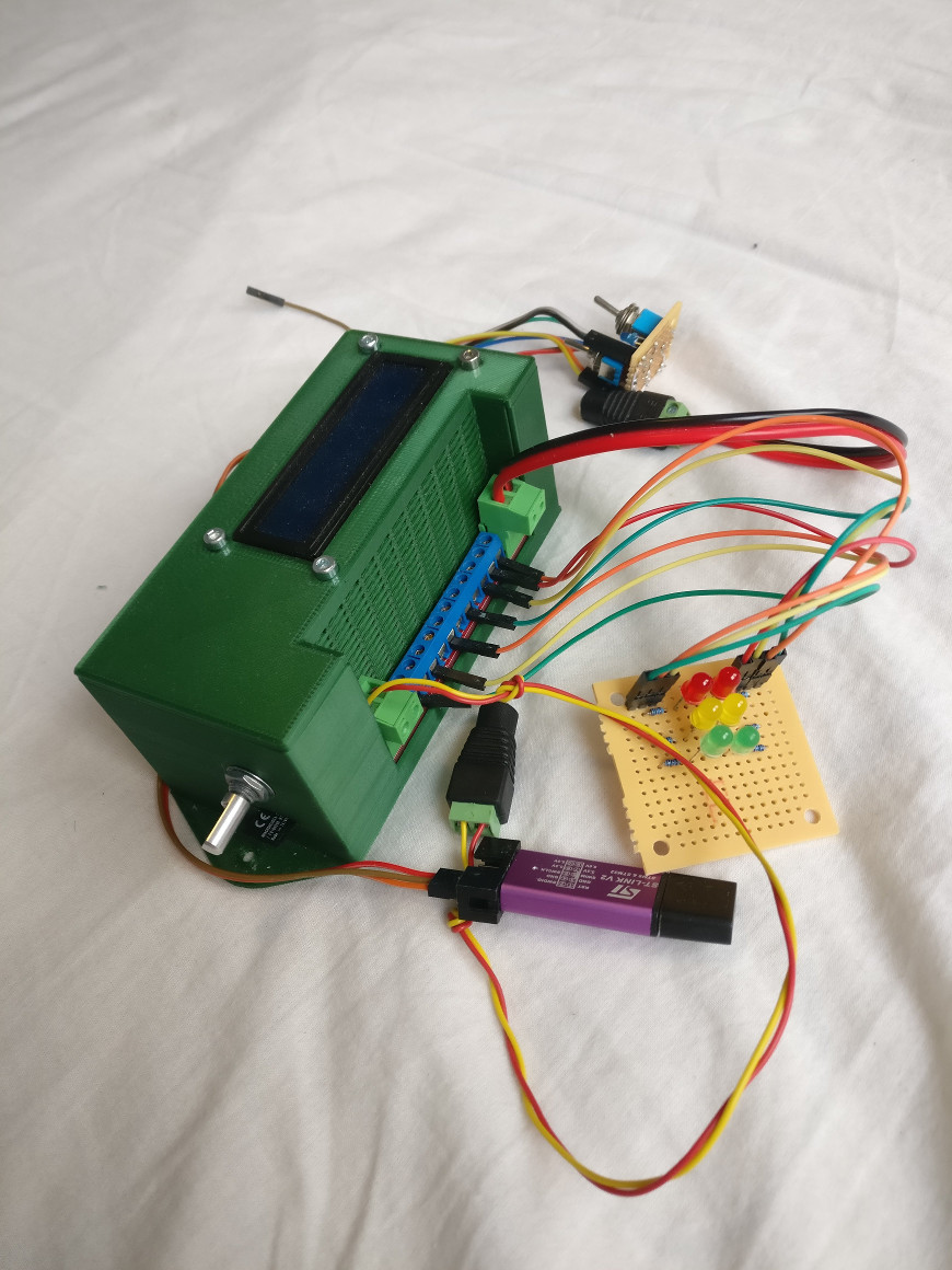
Prototype of STM32 based version
Arduino Nano based firware was built on Arduino framework using Sloeber Arduino IDE. Source files persist in folders named "gatekeeper", "common" and "libs".
STM32 version is completely separated as it is based on STM32Cube framework. STM32 sources are placed in "gatekeeper-stm32" and "stm32goodies" folder.
Arduino based first version hardware developed using proprietrary Eagle free version, and obsoleted by STM32 version but schematics of the mainboard and the IO panel are still available for reference.
As mentioned above, hardware of STM32 version designed using KiCAD. The complete EDA project is available in the hardware/STM32 folder. Here are the schematics in PDF for easier access.
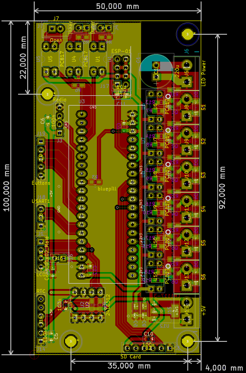
PCB design for STM32 bsed version
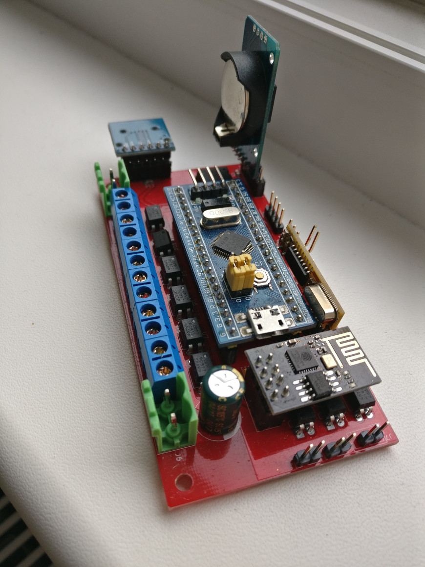
Assembled STM32 panel with modules installed
| Qty | Value | Footprint | References |
|---|---|---|---|
| 14 | 4.7k | Resistors_SMD:R_0603_HandSoldering | R1, R2, R13, R14, R15, R16, R17, R18, R19, R20, R21, R22, R23, R24 |
| 9 | 470 | Resistors_SMD:R_0603_HandSoldering | R4, R5, R6, R7, R8, R9, R10, R11, R12 |
| 7 | 100n | Capacitors_SMD:C_0805 | C3, C4, C5, C6, C7, C10, C12 |
| 6 | 1N4148 | Diodes_SMD:D_MiniMELF | D1, D2, D3, D4, D5, D6 |
| 6 | IRLML2502 | TO_SOT_Packages_SMD:SOT-23 | Q1, Q2, Q3, Q4, Q5, Q6 |
| 6 | PC817 | Housings_DIP:DIP-4_W7.62mm | U6, U7, U8, U9, U10, U11 |
| 3 | 10u | Capacitors_Tantalum_SMD:CP_Tantalum_Case-A_EIA-3216-18_Reflow | C8, C9, C11 |
| 3 | PC817 | Housings_DIP:DIP-4_W7.62mm_LongPads | U1, U4, U5 |
| 1 | +5V | TerminalBlock:TerminalBlock_bornier-2_P5.08mm | J15 |
| 1 | 1.8k | Resistors_SMD:R_0603_HandSoldering | R3 |
| 1 | 220u | Capacitors_THT:CP_Radial_D10.0mm_P3.50mm | C1 |
| 1 | 24LC512 | Housings_DIP:DIP-8_W7.62mm_LongPads | U2 |
| 1 | Buttons | Pin_Headers:Pin_Header_Straight_1x05_Pitch2.54mm | J19 |
| 1 | Conn_01x02_Male | Pin_Headers:Pin_Header_Straight_1x02_Pitch2.54mm | J16 |
| 1 | ESP-01 | Socket_Strips:Socket_Strip_Straight_2x04_Pitch2.54mm | J17 |
| 1 | Inner | Pin_Headers:Pin_Header_Straight_1x02_Pitch2.54mm | J5 |
| 1 | LCD | Pin_Headers:Pin_Header_Straight_1x04_Pitch2.54mm | J1 |
| 1 | LED Power | TerminalBlock:TerminalBlock_bornier-2_P5.08mm | J6 |
| 1 | LM1117-3.3 | TO_SOT_Packages_SMD:SOT-223 | U12 |
| 1 | Open | Connectors_JST:JST_EH_B02B-EH-A_02x2.50mm_Straight | J7 |
| 1 | Outer | Pin_Headers:Pin_Header_Straight_1x02_Pitch2.54mm | J4 |
| 1 | RTC | Pin_Headers:Pin_Header_Straight_1x06_Pitch2.54mm | J14 |
| 1 | Radio | Pin_Headers:Pin_Header_Straight_1x04_Pitch2.54mm | J3 |
| 1 | S1 | TerminalBlock:TerminalBlock_bornier-2_P5.08mm | J8 |
| 1 | S2 | TerminalBlock:TerminalBlock_bornier-2_P5.08mm | J9 |
| 1 | S3 | TerminalBlock:TerminalBlock_bornier-2_P5.08mm | J10 |
| 1 | S4 | TerminalBlock:TerminalBlock_bornier-2_P5.08mm | J11 |
| 1 | S5 | TerminalBlock:TerminalBlock_bornier-2_P5.08mm | J12 |
| 1 | S6 | TerminalBlock:TerminalBlock_bornier-2_P5.08mm | J13 |
| 1 | SD Card | Pin_Headers:Pin_Header_Straight_1x06_Pitch2.54mm | J2 |
| 1 | USART1 | Pin_Headers:Pin_Header_Straight_1x03_Pitch2.54mm | J18 |
| 1 | bluepill | bluepill:bluepill | U3 |
The 78 most common of 82 parts.
jcksnvllxr80/raspi_pico_christmas_tree
This project was designed for a decorative Christmas tree made out of cedar which stands about two feet in height.

freeDSP/SigmaLink-USBi
The freeDSP SigmaLink USBi PROGRAMMER is an all-in-one real-time programming interface.


Michael-Manning/E-Paper-Climate-Logger
Firmware, PCB, and enclosure for the Weathergotchi E-Paper climate logger.
It measures 50 × 100 mm and has 2 copper layers, 1.6 mm thick.
82 parts, built around the ESP-01, 24LC512-I/P, LM1117-3.3 and IRLML2502. The full list of its parts is on this page, with links to each part's symbol and footprint where PCBKit's library has them.
From the attilabody/gate433 repository on GitHub, at the commit this page was made from: the board is hardware/stm32/bluepill.kicad_pcb. PCBKit opens the board in the browser, with nothing to install.
Its repository states no licence, so its author keeps all rights: ask attilabody before reusing the design.