4 layers220 × 110 mm
Cell sim
atopile/cell-sim
This cell-sim is designed to mimic a LiPo battery pack for develpoment of the surrounding electronics, like a BMS.
1,152 parts25MIT

 atopile/cell-sim25
This cell-sim is designed to mimic a LiPo battery pack for develpoment of the surrounding electronics, like a BMS.
Level shifter is an open-source printed circuit board by atopile, from the atopile/cell-sim repository on GitHub, published under the MIT licence. It is a 2-layer board of 225.7 × 100.8 mm with 3 parts on 4 nets, routed with 6 tracks and 0 vias.
Its parts include 2 resistors and 1 IC. It belongs with the power and interfaces and adapters boards of this library.
This cell-sim is designed to mimic a LiPo battery pack for develpoment of the surrounding electronics, like a BMS.
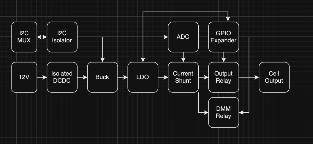
pip install -r requirements.txt
python example_set_voltages.py
You should see something like this:
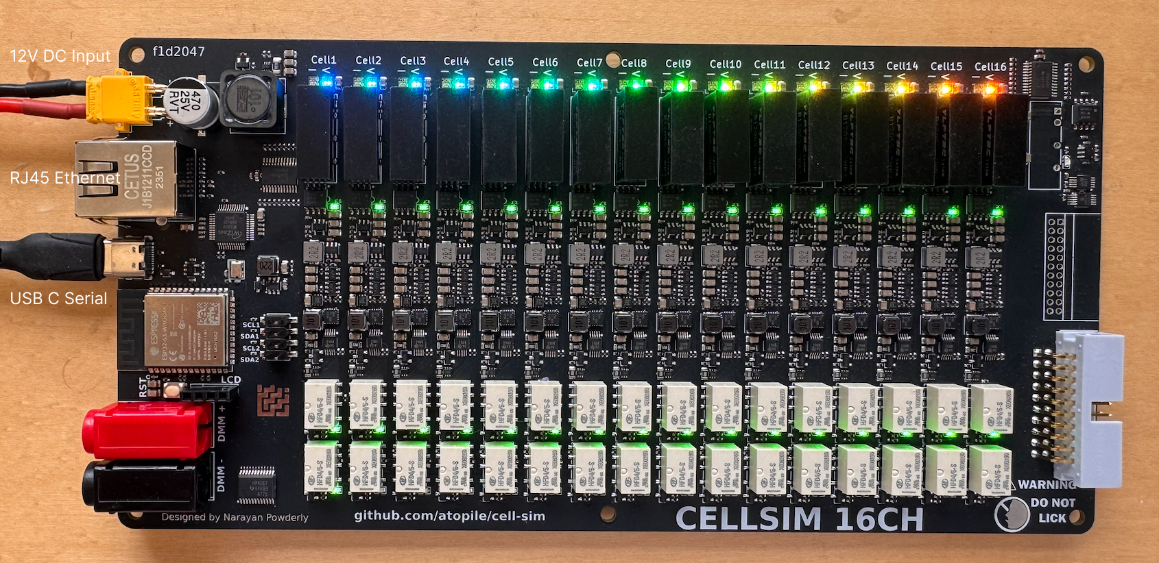
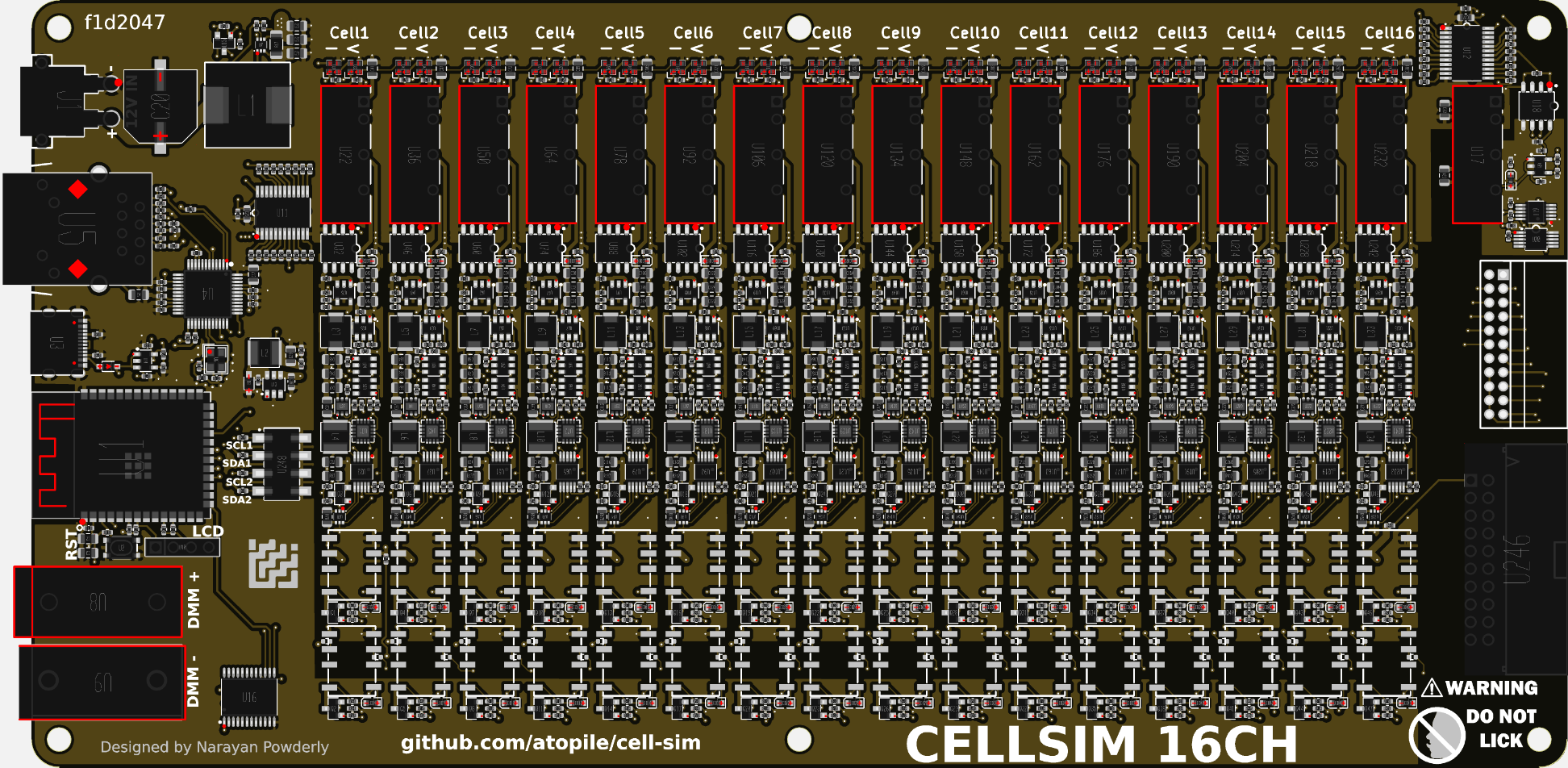
Board is intended to be manufactured with JLC, files are in the main directory of the repository. Note, the highlighted isolated regulator needs to be depopulated:
We use PlatformIO to build and upload the firmware via USB.
pio run -t upload or install the PlatformIO VSCode extension and use the upload button.from lib.cellsim import CellSim
cellsim = CellSim(port)Each cell has a relay in series between the cell output and the connector, this can be used to simulate open-wire faults for example.
# Global enable/disable
cellsim.enableOutputAll()
time.sleep(1)
cellsim.disableOutputAll()
time.sleep(1)

# Enable/disable one at a time
# Turn relays on in a wave
for i in range(1, 17):
    cellsim.enableOutput(i)
    time.sleep(0.1)

time.sleep(1)

# Turn relays off in a wave
for i in range(1, 17):
    cellsim.disableOutput(i)
time.sleep(0.1)Each output voltage can be specified between 0.5V and 4.4V
# Set all at once
cellsim.setAllVoltages(3.5)
time.sleep(1)

# Set one at a time
print("\nSetting rainbow voltage pattern...")
for i in range(16):
    voltage = 1.0 + (3.0 * i / 15)  # Spread 1V to 4V across 16 channels
cellsim.setVoltage(i + 1, voltage)Each channel has an onboard 16bit ADC that measures the cell output. Note this is not a kelvin connection to your DUT, the measurement will only be accurate when minimal current is being drawn by the DUT.
voltages = cellsim.getAllVoltages()
print(f"Voltages: {[f'{v:.3f}' for v in voltages]}")To take a precision measurement, each channel has a multiplexed output that connects to the DMM connector via a relay.
channel_to_measure = 3
# Enable DMM
cellsim.enableDMM(channel_to_measure)

# take measurment using external DMM
# that is connected to the DMM banana outputs
time.sleep(1)

cellsim.disableDMM()Each channel has a resistor + mosfet across its output, this can be used to speed up the discharge of the output capacitors. For example when transitioning from a high output voltage to a low output voltage, there will be an RC decay time before the voltage settles, typically in the ~100ms range. Turning on the load switch will make this much faster.
cellsim.enableLoadSwitchAll()
time.sleep(1)

cellsim.disableLoadSwitchAll()
time.sleep(1)Once your test is finished, you can use the following to close the serial session:
cellsim.close()| Qty | Value | Footprint | References |
|---|---|---|---|
| 2 | Chip Resistor - Surface Mount 10KOhms ±5% 1/16W 0402 RoHS | lib:R0402 | R1, R2 |
| 1 | lib:SOT-23-3_L2.9-W1.3-P1.90-LS2.4-BR | U1 |
It measures 225.7 × 100.8 mm and has 2 copper layers, 1.6 mm thick.
3 parts. The full list of its parts is on this page, with links to each part's symbol and footprint where PCBKit's library has them.
From the atopile/cell-sim repository on GitHub, at the commit this page was made from: the board is elec/src/components/level-shifter/elec/layout/default/level-shifter.kicad_pcb and its schematic elec/layout/cell/cell.kicad_sch. PCBKit opens the board in the browser, with nothing to install.
Its repository publishes it under the MIT licence: you may reuse it on that licence's terms (keep the author's notice, and for a copyleft licence share your changes alike).
atopile/cell-sim
This cell-sim is designed to mimic a LiPo battery pack for develpoment of the surrounding electronics, like a BMS.

atopile/cell-sim
This cell-sim is designed to mimic a LiPo battery pack for develpoment of the surrounding electronics, like a BMS.

atopile/cell-sim
This cell-sim is designed to mimic a LiPo battery pack for develpoment of the surrounding electronics, like a BMS.

atopile/cell-sim
This cell-sim is designed to mimic a LiPo battery pack for develpoment of the surrounding electronics, like a BMS.

atopile/cell-sim
This cell-sim is designed to mimic a LiPo battery pack for develpoment of the surrounding electronics, like a BMS.


hzeller/rpi-rgb-led-matrix
Controlling up to three chains of 64x64, 32x32, 16x32 or similar RGB LED displays using Raspberry Pi GPIO


atopile/atopile
Design circuit boards with code! ✨ Get software-like design reuse 🚀, validation, version control and collaboration in hardware; starting with electronics ⚡️


hackclub/sprig
🍃 Learn to code by making games in a JavaScript web-based game editor.