4 layers220 × 110 mm
Cell sim
atopile/cell-sim
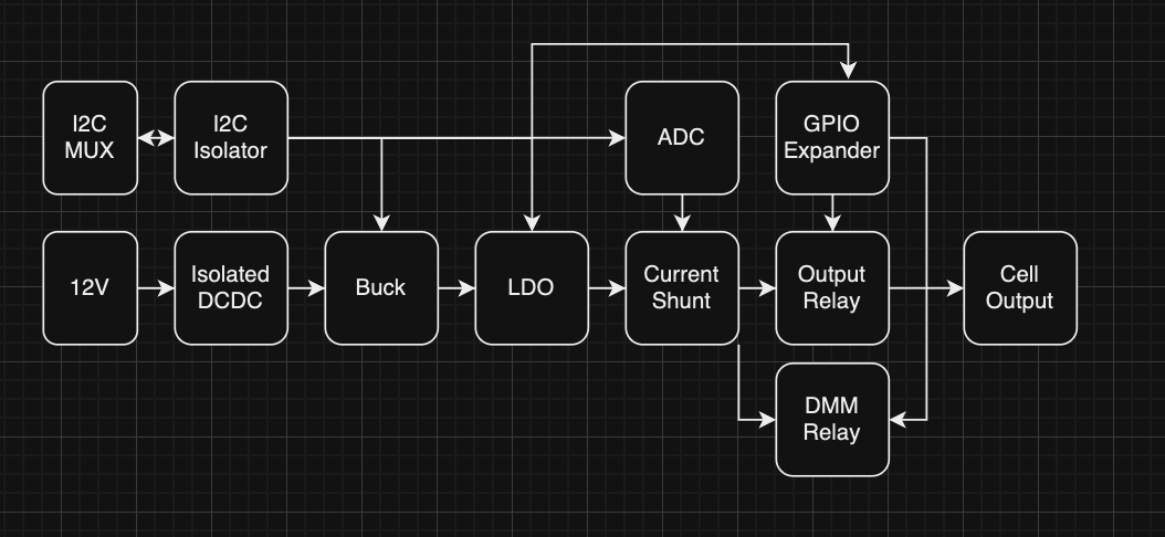
This cell-sim is designed to mimic a LiPo battery pack for develpoment of the surrounding electronics, like a BMS.
1,152 parts25MIT

 atopile/cell-sim25
This cell-sim is designed to mimic a LiPo battery pack for develpoment of the surrounding electronics, like a BMS.
Ethernet is an open-source printed circuit board by atopile, from the atopile/cell-sim repository on GitHub, published under the MIT licence. It is a 2-layer board with 32 parts on 37 nets, routed with 164 tracks and 18 vias.
Its parts include 16 capacitors, 13 resistors and 3 ICs. It belongs with the power and interfaces and adapters boards of this library.
This cell-sim is designed to mimic a LiPo battery pack for develpoment of the surrounding electronics, like a BMS.
pip install -r requirements.txt
python example_set_voltages.py
You should see something like this:
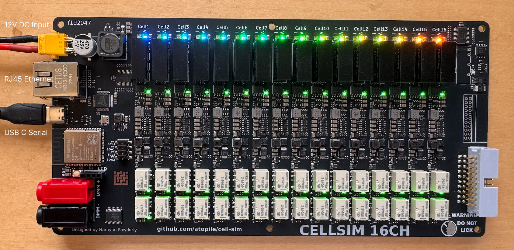
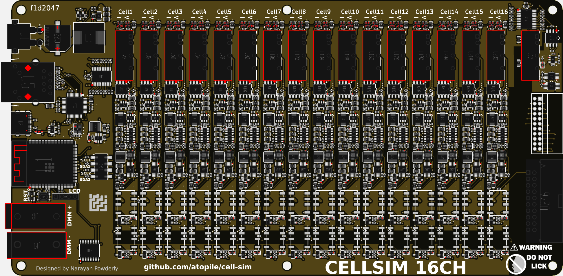
Board is intended to be manufactured with JLC, files are in the main directory of the repository. Note, the highlighted isolated regulator needs to be depopulated:
We use PlatformIO to build and upload the firmware via USB.
pio run -t upload or install the PlatformIO VSCode extension and use the upload button.from lib.cellsim import CellSim
cellsim = CellSim(port)Each cell has a relay in series between the cell output and the connector, this can be used to simulate open-wire faults for example.
# Global enable/disable
cellsim.enableOutputAll()
time.sleep(1)
cellsim.disableOutputAll()
time.sleep(1)

# Enable/disable one at a time
# Turn relays on in a wave
for i in range(1, 17):
    cellsim.enableOutput(i)
    time.sleep(0.1)

time.sleep(1)

# Turn relays off in a wave
for i in range(1, 17):
    cellsim.disableOutput(i)
time.sleep(0.1)Each output voltage can be specified between 0.5V and 4.4V
# Set all at once
cellsim.setAllVoltages(3.5)
time.sleep(1)

# Set one at a time
print("\nSetting rainbow voltage pattern...")
for i in range(16):
    voltage = 1.0 + (3.0 * i / 15)  # Spread 1V to 4V across 16 channels
cellsim.setVoltage(i + 1, voltage)Each channel has an onboard 16bit ADC that measures the cell output. Note this is not a kelvin connection to your DUT, the measurement will only be accurate when minimal current is being drawn by the DUT.
voltages = cellsim.getAllVoltages()
print(f"Voltages: {[f'{v:.3f}' for v in voltages]}")To take a precision measurement, each channel has a multiplexed output that connects to the DMM connector via a relay.
channel_to_measure = 3
# Enable DMM
cellsim.enableDMM(channel_to_measure)

# take measurment using external DMM
# that is connected to the DMM banana outputs
time.sleep(1)

cellsim.disableDMM()Each channel has a resistor + mosfet across its output, this can be used to speed up the discharge of the output capacitors. For example when transitioning from a high output voltage to a low output voltage, there will be an RC decay time before the voltage settles, typically in the ~100ms range. Turning on the load switch will make this much faster.
cellsim.enableLoadSwitchAll()
time.sleep(1)

cellsim.disableLoadSwitchAll()
time.sleep(1)Once your test is finished, you can use the following to close the serial session:
cellsim.close()| Qty | Value | Footprint | References |
|---|---|---|---|
| 6 | 16V 100nF X7R ±10% 0402 Multilayer Ceramic Capacitors MLCC - SMD/SMT ROHS | lib:C0402 | C8, C9, C10, C11, C12, C13 |
| 4 | 62.5mW Thick Film Resistors 50V ±100ppm/℃ ±1% 33Ω 0402 Chip Resistor - Surface Mount ROHS | lib:R0402 | R3, R4, R8, R9 |
| 4 | 62.5mW Thick Film Resistors 50V ±100ppm/℃ ±1% 49.9Ω 0402 Chip Resistor - Surface Mount ROHS | lib:R0402 | R5, R6, R10, R11 |
| 2 | 50V 10nF X7R ±10% 0402 Multilayer Ceramic Capacitors MLCC - SMD/SMT ROHS | lib:C0402 | C5, C6 |
| 2 | 50V 10pF C0G ±5% 0402 Multilayer Ceramic Capacitors MLCC - SMD/SMT ROHS | lib:C0402 | C15, C16 |
| 2 | 50V 6.8nF X7R ±10% 0402 Multilayer Ceramic Capacitors MLCC - SMD/SMT ROHS | lib:C0402 | C3, C4 |
| 2 | 62.5mW Thick Film Resistors 50V ±100ppm/℃ ±1% 200Ω 0402 Chip Resistor - Surface Mount ROHS | lib:R0402 | R1, R2 |
| 1 | 10V 4.7uF X5R ±20% 0402 Multilayer Ceramic Capacitors MLCC - SMD/SMT ROHS | lib:C0402 | C7 |
| 1 | 25V 10uF X5R ±10% 0805 Multilayer Ceramic Capacitors MLCC - SMD/SMT ROHS | lib:C0805 | C14 |
| 1 | 50V 1nF X7R ±10% 0805 Multilayer Ceramic Capacitors MLCC - SMD/SMT ROHS | lib:C0805 | C1 |
| 1 | 50V 22nF X7R ±10% 0402 Multilayer Ceramic Capacitors MLCC - SMD/SMT ROHS | lib:C0402 | C2 |
| 1 | 62.5mW Thick Film Resistors 50V ±1% ±200ppm/℃ 10Ω 0402 Chip Resistor - Surface Mount ROHS | lib:R0402 | R7 |
| 1 | 62.5mW Thick Film Resistors 50V ±100ppm/℃ ±1% 12.4kΩ 0402 Chip Resistor - Surface Mount ROHS | lib:R0402 | R12 |
| 1 | 62.5mW Thick Film Resistors 50V ±100ppm/℃ ±1% 1MΩ 0402 Chip Resistor - Surface Mount ROHS | lib:R0402 | R13 |
| 1 | ? | lib:LQFP-48_L7.0-W7.0-P0.50-LS9.0-BL | U1 |
| 1 | ? | lib:RJ45-TH_J1B1211CCD | U2 |
| 1 | ? | lib:CRYSTAL-SMD_4P-L3.2-W2.5-BL | U3 |
atopile/cell-sim
This cell-sim is designed to mimic a LiPo battery pack for develpoment of the surrounding electronics, like a BMS.

atopile/cell-sim
This cell-sim is designed to mimic a LiPo battery pack for develpoment of the surrounding electronics, like a BMS.

atopile/cell-sim
This cell-sim is designed to mimic a LiPo battery pack for develpoment of the surrounding electronics, like a BMS.

atopile/cell-sim
This cell-sim is designed to mimic a LiPo battery pack for develpoment of the surrounding electronics, like a BMS.

atopile/cell-sim
This cell-sim is designed to mimic a LiPo battery pack for develpoment of the surrounding electronics, like a BMS.

hoglet67/RGBtoHDMI
Bare-metal Raspberry Pi project that provides pixel-perfect sampling of Retro Computer RGB/YUV video and conversion to HDMI

hackclub/OnBoard
💡 Join 1,000 teenagers and make your first PCB with a $100 grant!


octosavvi/ESPKey
Wiegand data logger, replay device and micro door-controller

zmaker/arduino_cookbook
gli sketch del nuovo progetto Arduino Cookbook e dei video di YouTube

murexrobotics/electrical
Highly integrated electronics design and printed circuit boards (PCBs) for the MATE ROV Competition. Attempt the impossible.

swharden/AVR-projects
A collection of standalone AVR projects written in C

hardenedlinux/cheap-pcb
Cheap PCB: Better understanding the current status of hardware supply chain
32 parts. The full list of its parts is on this page, with links to each part's symbol and footprint where PCBKit's library has them.
From the atopile/cell-sim repository on GitHub, at the commit this page was made from: the board is elec/layout/ethernet/ethernet.kicad_pcb and its schematic elec/layout/cell/cell.kicad_sch. PCBKit opens the board in the browser, with nothing to install.
Its repository publishes it under the MIT licence: you may reuse it on that licence's terms (keep the author's notice, and for a copyleft licence share your changes alike).