2 layers61 × 62 mm

 atanisoft/Esp32OlcbIO12
ESP32 OpenLCB IO Board
Esp32OlcbIO is an open-source printed circuit board by atanisoft, from the atanisoft/Esp32OlcbIO repository on GitHub. It is a 4-layer board of 61 × 81 mm with 52 parts on 46 nets, routed with 315 tracks and 35 vias.
It is built around the TJA1051T/3/1, AP63205WU and LM358, with the RJ45 and NUP2105L among its other parts. Its parts include 13 capacitors, 8 resistors, 7 connectors, 5 ICs and 5 diodes. It belongs with the ESP32 boards of this library.


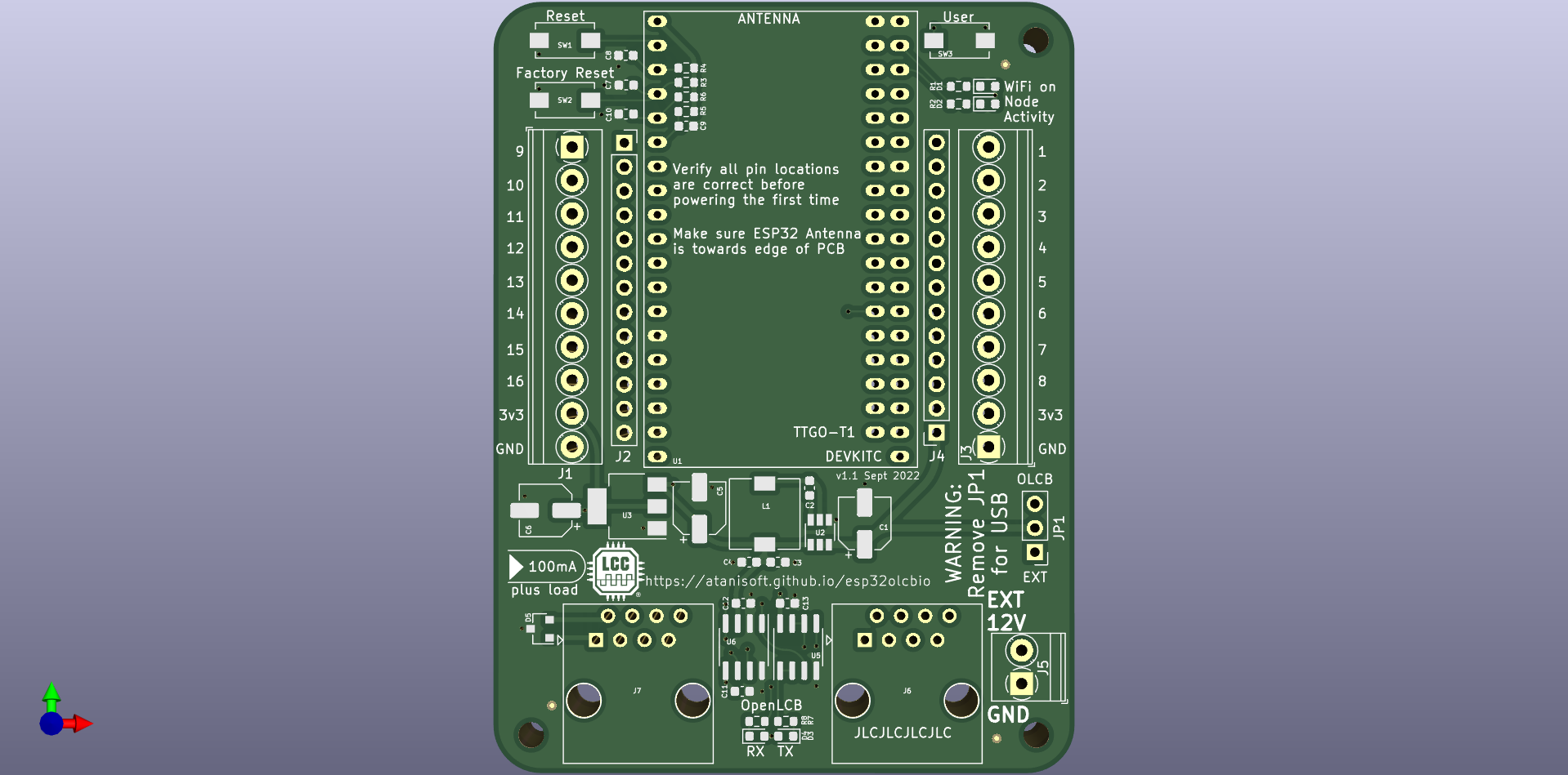
The ESP32 OpenLCB IO Board is a basic OpenLCB (LCC) node offering 14 input/output capable pins, and two that are input only. Additionally all IO pins are exposed through two 13 pin headers which allows for extending the functionality of the base board using a daughter board approach.
The ESP32 OpenLCB IO Board can be powered from an external power supply (12V) on J5 connector, or using the OpenLCB (LCC) Bus power on RJ45. To enable powering from the external supply, bridge pins 1 and 2 on JP1. To power from the OpenLCB (LCC) Bus, bridge pins 2 and 3. Note that when using the USB connector on the ESP32 module JP1 should not have any pins bridged.
The ESP32 OpenLCB IO Board will draw around 100mA from the OpenLCB (LCC) Bus when the PWR_POS pin provides 15VDC. If the PWR_POS pin provides less, the node may draw more current from the bus.
The external power supply should be rated for at least 12VDC 500mA to ensure sufficient current is available for the node to operate as intended.
If the ESP32 detects a brownout condition it will attempt to produce the
well-known event 01.00.00.00.00.00.FF.F1 soon after startup. This delivery
is not guaranteed.
By default almost all pins are exposed for general IO usage by the node, however a few pins have specialized usage as part of the screw terminals or expansion headers.
| GPIO Pin | Usage | Notes |
|---|---|---|
| 0 | IO4 | has pull-up resistor |
| 1 | UART0 TX | not exposed |
| 2 | IO5 | has pull-down resistor |
| 3 | UART0 RX | not exposed |
| 4 | CAN RX | has pull-down resistor |
| 5 | CAN TX | has pull-up resistor |
| 6-11 | NOT AVAILABLE | connected to on chip flash |
| 12 | IO7 | has pull-down resistor |
| 13 | IO8 | |
| 14 | IO16 | |
| 15 | IO6 | has pull-up resistor |
| 16 | IO3 | |
| 17 | IO2 | |
| 18 | IO1 | |
| 19 | I2C - SDA | |
| 20 | NOT AVAILABLE | NOT AVAILABLE |
| 21 | I2C - SCL | |
| 22 | Node Activity LED | active low |
| 23 | WiFi Active LED | active low |
| 24 | NOT AVAILABLE | NOT AVAILABLE |
| 25 | IO13 | |
| 26 | IO14 | |
| 27 | IO15 | |
| 28-31 | NOT AVAILABLE | NOT AVAILABLE |
| 32 | IO11 | |
| 33 | IO12 | |
| 34 | IO9 | INPUT ONLY, has pull-up resistor |
| 35 | IO10 | INPUT ONLY |
| 36 (SVP) | User button | INPUT ONLY, has pull-up resistor |
| 37 | NOT AVAILABLE | NOT AVAILABLE |
| 38 | NOT AVAILABLE | NOT AVAILABLE |
| 39 (SVP) | Factory Reset button | INPUT ONLY, has pull-up resistor |
The four pins marked as INPUT ONLY in the table above have a 10k pull-up to 3v3 and a 100nF capacitor for debounce.
IO4 and IO6 typically have a pull-up resistor. IO5 and IO7 typically have a pull-down resistor that can not be disabled. Keep this in mind as this may require adjustments to usage patterns.
The ESP32 OpenLCB IO Board PCB can be found under the pcb directory and is provided as both KiCad files and generated Gerber files.
NOTE: U6 (CAN Transceiver) BOM line item references IFX1050GVIOXUMA1 which is no longer in production, please use one of the following instead:
The ESP32 OpenLCB IO PCB has been shared via PCBWay here.
The ESP32 OpenLCB IO Board components have been entered on Mouser for easy ordering via the following shared carts:
Ordering in larger quantities can decrease the per-PCB cost considerably. In the case of resistors and capacitors it is recommended to order 100 of each as they are tiny and easily lost. Other parts can often be substituted as long as they have the same footprint and pinout. The pin headers will need to be cut to length in both of the carts above, in the case of the five PCBs option there should be enough to populate all five PCBs for the ESP32 AND the extension board (when available).
The following parts are optional depending on board usage:
| Part | Mouser # | Notes |
|---|---|---|
| J2, J4 | 571-6-534237-1 | These are only needed for attaching an extension daughter board. |
| J5 | 523-NY0210800000G | This is only required if using an external power supply. |
The following parts have compatible alternatives:
| Part | Default Mouser # | Alternative Mouser # | Notes |
|---|---|---|---|
| J2, J4 | 571-6-534237-1 | 992-13FX1-254MM, 485-598, 485-4158, 485-4156, 485-4159, 485-4157, 485-4155, 485-4160 | Parts 485-XXXX will need to be cut to the correct length. |
| J6, J7 | 571-5569284-1 | 534-949 or 493-HCJV1-812UK |
The ESP32 OpenLCB IO Board can be extended by using the pcb-ext daughter board files as a basis for creating a compatible extension PCB. This PCB sits on top of the base board.
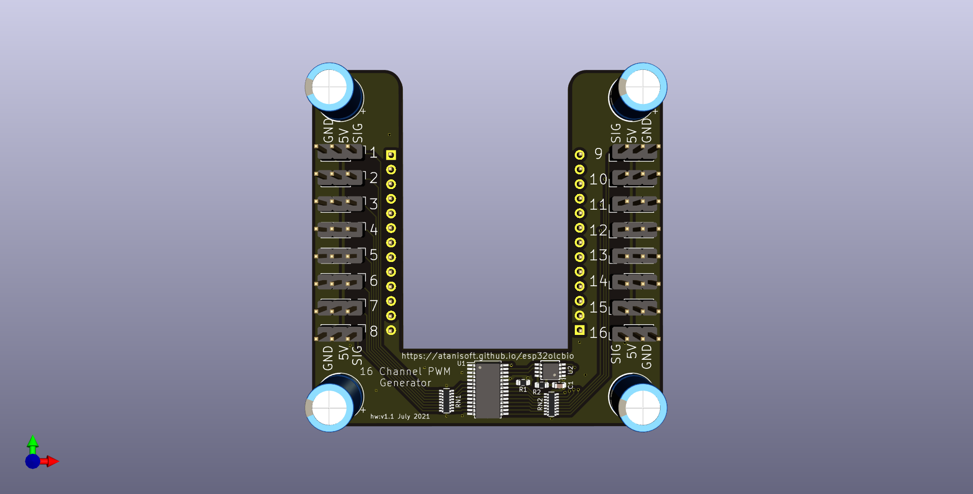
The first expansion board is the 16 Channel PWM generator board, this is usable for Servo or LED control. This expansion board utilizes a PCA9685 to generate 16 PWM signals which are routed to a three pin header (GND, 5V and PWM) for each output.
| Qty | Value | Footprint | References |
|---|---|---|---|
| 8 | 100nF | Capacitor_SMD:C_0603_1608Metric | C2, C7, C8, C9, C10, C11, C12, C13 |
| 4 | 10k | Resistor_SMD:R_0603_1608Metric | R3, R4, R5, R6 |
| 4 | 160R | Resistor_SMD:R_0603_1608Metric | R1, R2, R7, R8 |
| 3 | 10uF | Capacitor_SMD:CP_Elec_5x5.3 | C1, C5, C6 |
| 3 | Fiducial | Fiducial:Fiducial_0.5mm_Mask1mm | FID1, FID2, FID3 |
| 3 | MountingHole | MountingHole:MountingHole_2.7mm_M2.5 | H1, H2, H3 |
| 2 | 22uF | Capacitor_SMD:C_0603_1608Metric | C3, C4 |
| 2 | RJ45 | Connector_RJ:RJ45_OST_PJ012-8P8CX_Vertical | J6, J7 |
| 1 | 4.7uH | Inductor_SMD:L_7.3x7.3_H4.5 | L1 |
| 1 | AP2114-3.3 | Package_TO_SOT_SMD:SOT-223-3_TabPin2 | U3 |
| 1 | AP63205WU | Package_TO_SOT_SMD:TSOT-23-6 | U2 |
| 1 | Activity | LED_SMD:LED_0603_1608Metric | D2 |
| 1 | CAN RX | LED_SMD:LED_0603_1608Metric | D4 |
| 1 | CAN TX | LED_SMD:LED_0603_1608Metric | D3 |
| 1 | ESP32-Module | Components:TTGO-T1-DEVKIT-C | U1 |
| 1 | EXT POWER | TerminalBlock_Phoenix:TerminalBlock_Phoenix_PT-1,5-2-3.5-H_1x02_P3.50mm_Horizontal | J5 |
| 1 | Factory Reset | Button_Switch_SMD:SW_SPST_EVQPE1 | SW2 |
| 1 | LEFT | TerminalBlock_Phoenix:TerminalBlock_Phoenix_PT-1,5-10-3.5-H_1x10_P3.50mm_Horizontal | J1 |
| 1 | LEFT-EXT | Connector_PinSocket_2.54mm:PinSocket_1x13_P2.54mm_Vertical | J2 |
| 1 | LM358 | Package_SO:SOIC-8_3.9x4.9mm_P1.27mm | U5 |
| 1 | LOGO | Components:lcc-logo-registered-medium | G*** |
| 1 | NUP2105L | Package_TO_SOT_SMD:SOT-23 | D5 |
| 1 | RIGHT | TerminalBlock_Phoenix:TerminalBlock_Phoenix_PT-1,5-10-3.5-H_1x10_P3.50mm_Horizontal | J3 |
| 1 | RIGHT-EXT | Connector_PinSocket_2.54mm:PinSocket_1x13_P2.54mm_Vertical | J4 |
| 1 | Reset | Button_Switch_SMD:SW_SPST_EVQPE1 | SW1 |
| 1 | TJA1051T-3 | Package_SO:SOIC-8_3.9x4.9mm_P1.27mm | U6 |
| 1 | User | Button_Switch_SMD:SW_SPST_EVQPE1 | SW3 |
| 1 | VCC SOURCE | Connector_PinHeader_2.54mm:PinHeader_1x03_P2.54mm_Vertical | JP1 |
| 1 | WiFi | LED_SMD:LED_0603_1608Metric | D1 |
The 50 most common of 52 parts.
It measures 61 × 81 mm and has 4 copper layers, 4.69 mm thick.
52 parts, built around the TJA1051T/3/1, AP63205WU, LM358 and RJ45. The full list of its parts is on this page, with links to each part's symbol and footprint where PCBKit's library has them.
From the atanisoft/Esp32OlcbIO repository on GitHub, at the commit this page was made from: the board is pcb/pcb.kicad_pcb and its schematic pcb-servo/pcb-servo.kicad_sch. PCBKit opens the board in the browser, with nothing to install.
Its repository states no licence, so its author keeps all rights: ask atanisoft before reusing the design.


vsi5004/ReadingLampController
A repurposing of my LCC Lighting Controller hardware into a customizable, Matter enabled, RGBW reading lamp

maximus64/opendiag-hardware
OpenDIAG - Open Source OBD2 Interface (Hardware)

RobertPHeller/RPi-RRCircuits
A collection of circuit designs for various MCUs, not just Raspberry Pis relating to Model Railroading


FOME-Tech/Polygonus-Universal
Open source 88pin universal base (NOT A PNP)

padamsarda/MT_test_driver-PCB
magnetorquer driver PCB for simulations and selection
