


4 layers48.3 × 57.7 mm
Sensor node v1
asinghani/rp2040_aprs_sensor_node
RP2040-based sensor node PCB that communicates on the APRS (Automatic Packet Reporting System) network
57 parts2
 asinghani/drive-by-wireless
F22 Distributed Embedded Final Project: UWB Drive-by-Wireless
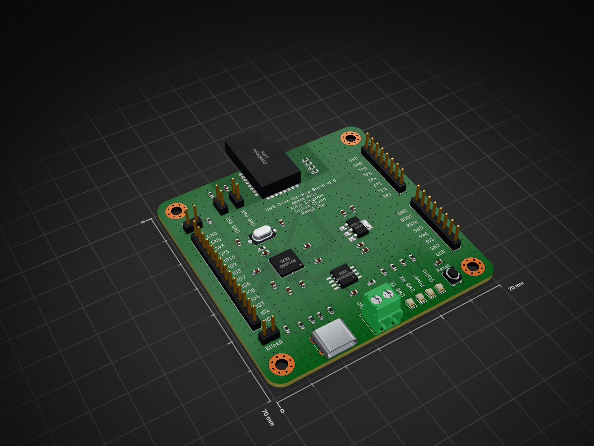
449pcb v1 is an open-source printed circuit board by asinghani, from the asinghani/drive-by-wireless repository on GitHub. It is a 4-layer board of 70 × 70 mm with 56 parts on 76 nets, routed with 454 tracks and 418 vias.
It is built around the RP2040, DWM3000 and ECS-120-20-3X-TR. Its parts include 17 resistors, 16 capacitors, 7 connectors, 4 ICs and 4 diodes. It belongs with the RP2040 boards of this library.
UWB drive-by-wireless
Clone pico-sdk and pico-extras and put them in your environment variables as PICO_SDK_PATH and PICO_EXTRAS_PATH. Also clone FreeRTOS-Kernel, smp branch and put its path as FREERTOS_KERNEL_PATH
cd firmware
rm -r build; mkdir build; cd build (its safest to delete and re-make the build directory every time because CMake caches things incorrectly sometimes)
cmake .. && make -j8 (this will build all 3 targets - cockpit, steering, and drivetrain)
This should yield zone_cockpit.uf2, zone_steering.uf2, and zone_drivetrain.uf2 which can be flashed to the boards.
- firmware/ (the directory for the firmware)
    - main.c (main entry point, shouldn't put any more code into this file)
    - utils.h (utility functions for math, safety, etc.)
    - config.h (configuration of GPIO pins, etc.)
    - FreeRTOSConfig.h
    - z_cockpit/
        - main_cockpit.c (entry point for cockpit zone)
    - z_drivetrain/
        - main_drivetrain.c (entry point for drivetrain zone)
    - z_steering/
        - main_steering.c (entry point for steering zone)
    - common/ (common stuff)
        - freertos_callbacks.c
    - peripherals/ (drivers for hardware peripherals)
        - testpoints.h (driver for test points)

- experimental/ (for test programs)

- scripts/ (scripts to run on a host machine)
    - proxy_gui.py (the steering wheel proxy, to run on Windows)

- hardware/ (hardware / CAD files)
    - 449pcb_v1/ (PCB CAD)
- schematic.pdf (board schematic, for easy reference)| Qty | Value | Footprint | References |
|---|---|---|---|
| 6 | 100n | Capacitor_SMD:C_0603_1608Metric | C5, C10, C13, C14, C15, C17 |
| 6 | 220R | Resistor_SMD:R_0603_1608Metric | R1, R2, R6, R8, R13, R14 |
| 5 | 47R | Resistor_SMD:R_0603_1608Metric | R5, R9, R10, R11, R12 |
| 4 | 1u | Capacitor_SMD:C_0603_1608Metric | C2, C4, C12, C16 |
| 4 | hole | MountingHole:MountingHole_3.2mm_M3_Pad_Via | H1, H2, H3, H4 |
| 2 | 10u | Capacitor_SMD:C_0603_1608Metric | C1, C6 |
| 2 | 1k | Resistor_SMD:R_0603_1608Metric | R7, R15 |
| 2 | 27R | Resistor_SMD:R_0603_1608Metric | R16, R17 |
| 2 | 27p | Capacitor_SMD:C_0603_1608Metric | C7, C8 |
| 2 | 5K1 | Resistor_SMD:R_0603_1608Metric | R3, R4 |
| 1 | 0.1u | Capacitor_SMD:C_0603_1608Metric | C9 |
| 1 | 22u | Capacitor_SMD:C_0603_1608Metric | C3 |
| 1 | AZ1117-3.3 | Package_TO_SOT_SMD:SOT-223-3_TabPin2 | U1 |
| 1 | BlinkL | Connector_PinHeader_2.54mm:PinHeader_1x02_P2.54mm_Vertical | J4 |
| 1 | BlinkR | Connector_PinHeader_2.54mm:PinHeader_1x02_P2.54mm_Vertical | J5 |
| 1 | DWM3000 | DWM3000:DWM3000 | U2 |
| 1 | DW_PWR | Connector_PinHeader_2.54mm:PinHeader_1x02_P2.54mm_Vertical | JP2 |
| 1 | DW_RST | Connector_PinHeader_2.54mm:PinHeader_1x02_P2.54mm_Vertical | JP1 |
| 1 | Debug | Connector_PinHeader_2.54mm:PinHeader_1x08_P2.54mm_Vertical | J7 |
| 1 | ECS-120-20-3X-TR | ECS-120-20-3X-TR:XTAL_ECS-120-20-3X-TR | Y1 |
| 1 | GD25Q128 | Package_SO:SOIC-8_5.23x5.23mm_P1.27mm | U3 |
| 1 | IO | Connector_PinHeader_2.54mm:PinHeader_1x14_P2.54mm_Vertical | J6 |
| 1 | PWR | LED_SMD:LED_0805_2012Metric | D4 |
| 1 | PwrScrew | TerminalBlock_4Ucon:TerminalBlock_4Ucon_1x02_P3.50mm_Horizontal | J2 |
| 1 | RP2040 | RP2040:RP2040-QFN-56 | U4 |
| 1 | RXLED | LED_SMD:LED_0805_2012Metric | D2 |
| 1 | Reset | Button_Switch_SMD:SW_SPST_PTS810 | SW1 |
| 1 | STATUS | LED_SMD:LED_0805_2012Metric | D3 |
| 1 | TXLED | LED_SMD:LED_0805_2012Metric | D1 |
| 1 | TestPts | Connector_PinHeader_2.54mm:PinHeader_1x08_P2.54mm_Vertical | J1 |
| 1 | USB_USER | USB_C_Receptacle_HRO_TYPE-C-31-M-12:USB_C_HRO-31-M-12_nofront | J3 |
asinghani/rp2040_aprs_sensor_node
RP2040-based sensor node PCB that communicates on the APRS (Automatic Packet Reporting System) network

asinghani/ibm-5151-controller
Building a VT100 emulator out of an IBM 5151 monitor and an FPGA


GrimGT/Meridian
Tagged ranging and coordinate position system for FRC events. Using UWB ranging with anchors and tags to provide realtime positioning of robots

manyetox/Autonomous-Photonics-Carrier
Source-available modular mobile carrier for autonomous photonics experiments using ESP32 control, optical flow, IMU sensing and magnetic wheel encoding.

victorstoica114/UWB_Module_ESP_IDF
ESP-IDF 6.0.2 firmware for the custom UWB Module V1.0 Rev.B, based on an ESP32-S3-WROOM-1-N16R8. The same application image runs on every module; persistent identity and runtime configuration select the role and active…

aniranaway/Drone_Swarm
A fully custom, low-level embedded hardware and firmware platform designed for autonomous multi drone swarms. The system integrates custom STM32-based flight controller PCBs, coreless DC motor drive arrays for a micro…

CaramelFur/UWB-RTLS-Node-PCB
CustomLibs has all custom libraries and 3D models used in this project. This is merged with GeneratedLibs, which contains all the libraries and 3D models from easyeda.
It measures 70 × 70 mm and has 4 copper layers, 1.6 mm thick.
56 parts, built around the RP2040, DWM3000 and ECS-120-20-3X-TR. The full list of its parts is on this page, with links to each part's symbol and footprint where PCBKit's library has them.
From the asinghani/drive-by-wireless repository on GitHub, at the commit this page was made from: the board is hardware/449pcb_v1/449pcb_v1.kicad_pcb and its schematic hardware/449pcb_v1/449pcb_v1.kicad_sch. PCBKit opens the board in the browser, with nothing to install.
Its repository states no licence, so its author keeps all rights: ask asinghani before reusing the design.