4 layers99.1 × 83.8 mm
Ibm-5151-pcb
asinghani/ibm-5151-controller
Building a VT100 emulator out of an IBM 5151 monitor and an FPGA
85 partsMIT
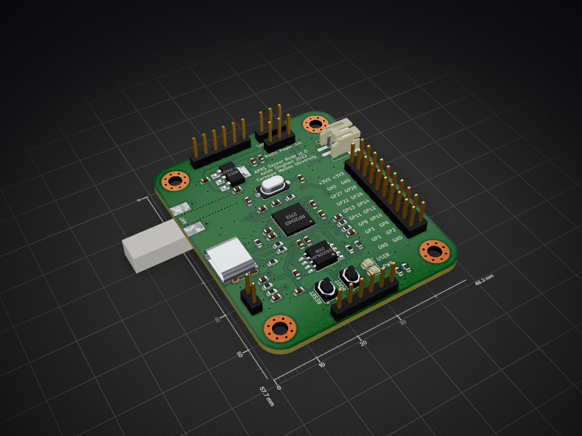
 asinghani/rp2040_aprs_sensor_node2
RP2040-based sensor node PCB that communicates on the APRS (Automatic Packet Reporting System) network
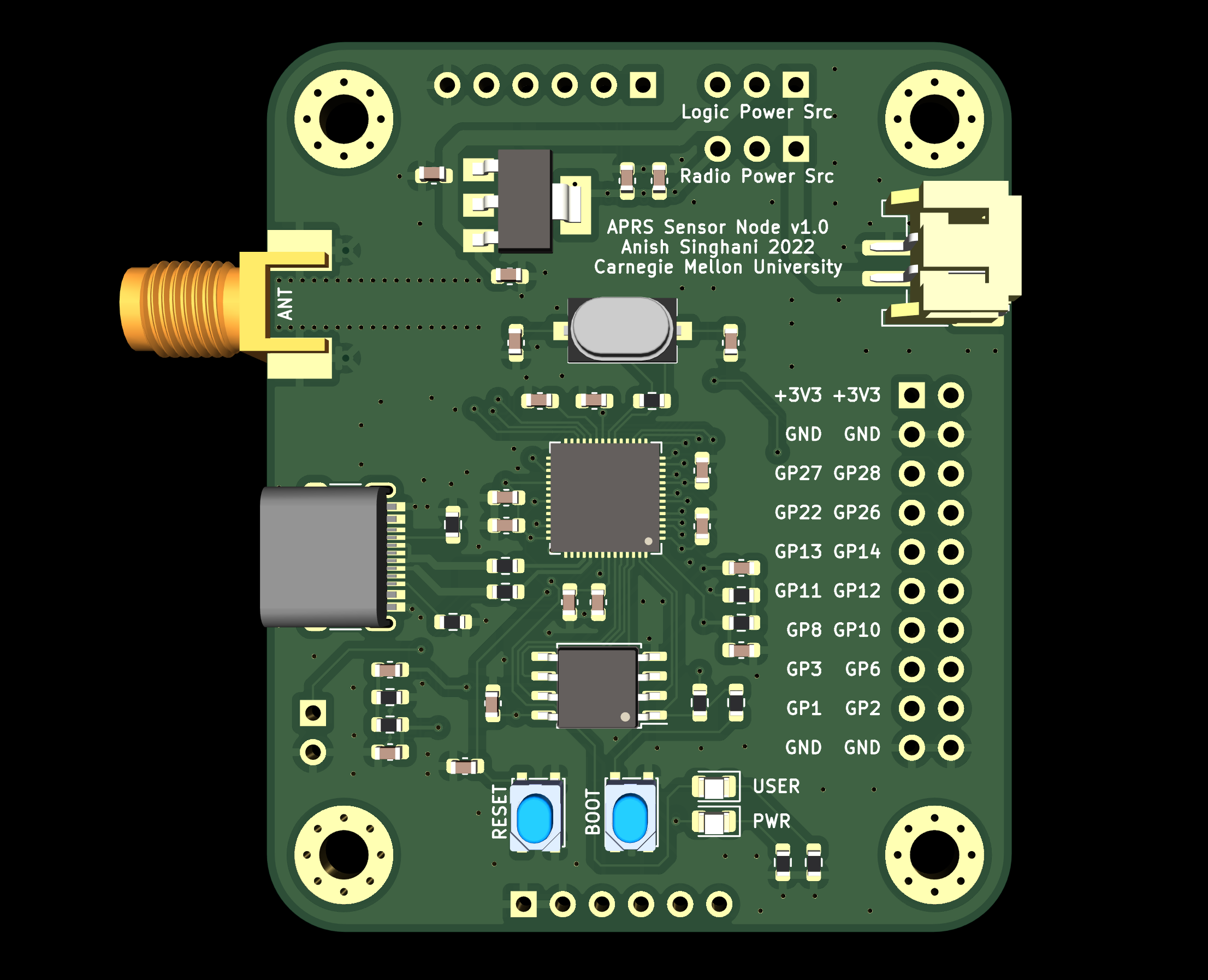
Sensor node v1 is an open-source printed circuit board by asinghani, from the asinghani/rp2040_aprs_sensor_node repository on GitHub. It is a 4-layer board of 48.3 × 57.7 mm with 57 parts on 69 nets, routed with 586 tracks and 181 vias.
It is built around the RP2040, W25Q128JVSIQ and ECS-120-20-3X-TR. Its parts include 20 capacitors, 13 resistors, 6 connectors, 4 ICs and 2 diodes. It belongs with the home automation and IoT and sensors and measurement boards and the RP2040 boards of this library.


Cheap, low-power embedded sensor-node powered by an RP2040 microcontroller that communicates over the APRS (Automatic Packet Reporting System) network using the VHF Amateur Radio band.
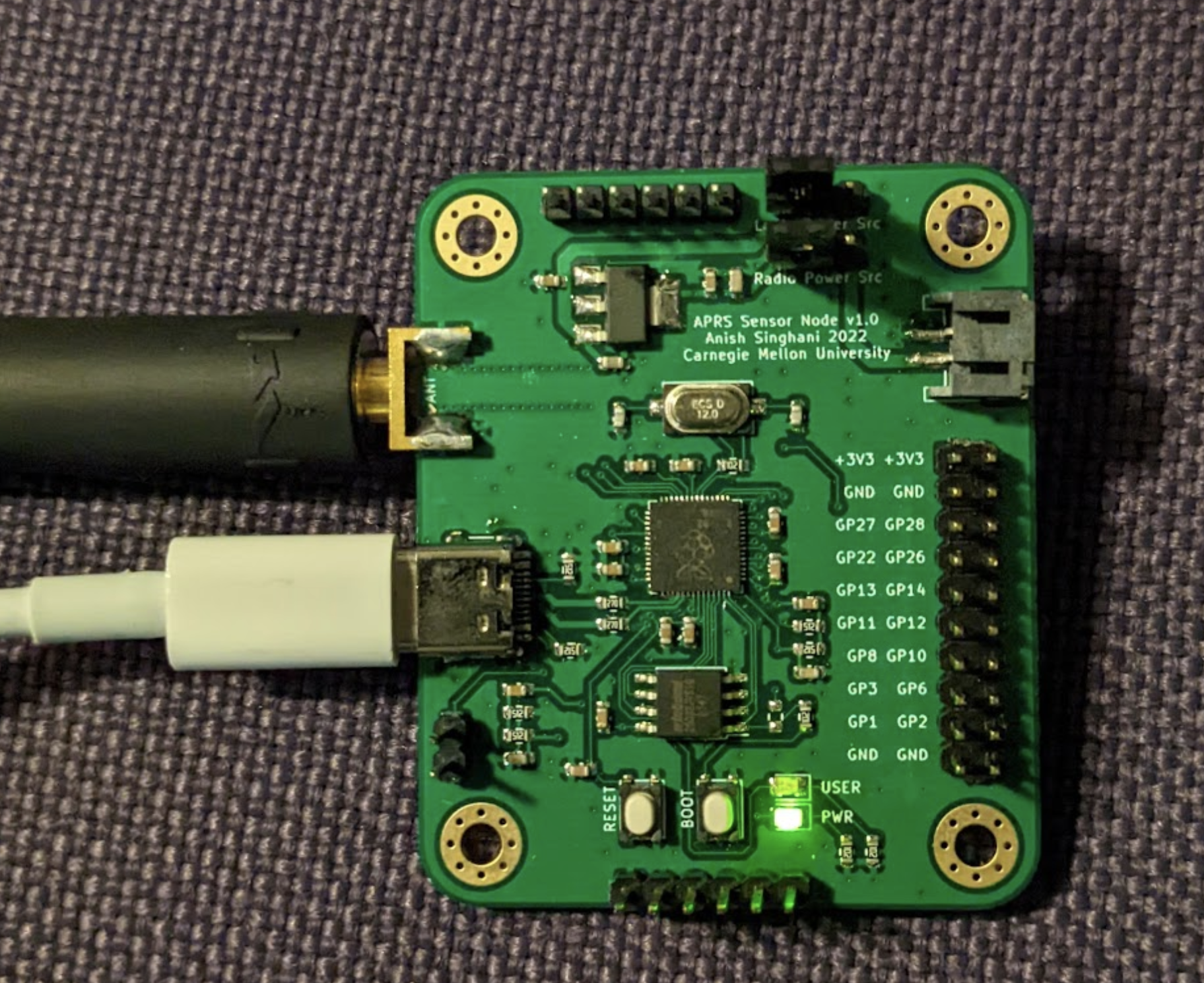
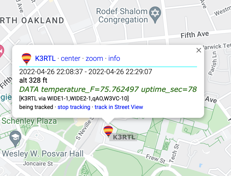
The directory firmware includes example code which reads from a TMP102 temperature sensor and transmits over the APRS network. The pinout for the sensor is defined in firmware/src/tmp102.c.
| Qty | Value | Footprint | References |
|---|---|---|---|
| 9 | 100n | Capacitor_SMD:C_0603_1608Metric | C5, C6, C7, C13, C14, C16, C17, C18, C20 |
| 4 | 1u | Capacitor_SMD:C_0603_1608Metric | C2, C4, C15, C19 |
| 4 | 5k1 | Resistor_SMD:R_0603_1608Metric | R5, R6, R7, R8 |
| 4 | MountingHole | MountingHole:MountingHole_3.2mm_M3_Pad_Via | H1, H2, H3, H4 |
| 2 | 10n | Capacitor_SMD:C_0603_1608Metric | C8, C9 |
| 2 | 1K | Resistor_SMD:R_0603_1608Metric | R9, R10 |
| 2 | 1k | Resistor_SMD:R_0603_1608Metric | R3, R11 |
| 2 | 27R | Resistor_SMD:R_0603_1608Metric | R12, R13 |
| 2 | 27p | Capacitor_SMD:C_0603_1608Metric | C11, C12 |
| 2 | 5K1 | Resistor_SMD:R_0603_1608Metric | R1, R2 |
| 2 | Debug | Connector_PinHeader_2.54mm:PinHeader_1x06_P2.54mm_Vertical | J6, J8 |
| 1 | 0.1u | Capacitor_SMD:C_0603_1608Metric | C10 |
| 1 | 10k, DNF | Resistor_SMD:R_0603_1608Metric | R4 |
| 1 | 10u | Capacitor_SMD:C_0603_1608Metric | C1 |
| 1 | 22u | Capacitor_SMD:C_0603_1608Metric | C3 |
| 1 | AZ1117-3.3 | Package_TO_SOT_SMD:SOT-223-3_TabPin2 | U2 |
| 1 | Antenna | Connector_Coaxial:SMA_Molex_73251-2120_EdgeMount_Horizontal | J3 |
| 1 | Boot Button | Button_Switch_SMD:SW_SPST_PTS810 | SW1 |
| 1 | Conn_01x02 | Connector_JST:JST_PH_S2B-PH-SM4-TB_1x02-1MP_P2.00mm_Horizontal | J5 |
| 1 | DRA818V | DRA818V:DORJI_DRA818V | U1 |
| 1 | ECS-120-20-3X-TR | ECS-120-20-3X-TR:XTAL_ECS-120-20-3X-TR | Y1 |
| 1 | GPIO Header | Connector_PinHeader_2.54mm:PinHeader_2x10_P2.54mm_Vertical | J1 |
| 1 | PWRLED | LED_SMD:LED_0805_2012Metric | D2 |
| 1 | Power Level | Connector_PinHeader_2.54mm:PinHeader_1x02_P2.54mm_Vertical | JP3 |
| 1 | RP2040 | RP2040:RP2040-QFN-56 | U4 |
| 1 | RX_JMP | Jumper:SolderJumper-2_P1.3mm_Bridged_Pad1.0x1.5mm | JP1 |
| 1 | Radio Power | Connector_PinHeader_2.54mm:PinHeader_1x03_P2.54mm_Vertical | JP5 |
| 1 | Reset | Button_Switch_SMD:SW_SPST_PTS810 | SW2 |
| 1 | System Power | Connector_PinHeader_2.54mm:PinHeader_1x03_P2.54mm_Vertical | JP4 |
| 1 | TX_JMP | Jumper:SolderJumper-2_P1.3mm_Bridged_Pad1.0x1.5mm | JP2 |
| 1 | USB_USER | USB_C_Receptacle_HRO_TYPE-C-31-M-12:USB_C_HRO-31-M-12_nofront | J2 |
| 1 | USERLED | LED_SMD:LED_0805_2012Metric | D1 |
| 1 | W25Q128JVS | Package_SO:SOIC-8_5.23x5.23mm_P1.27mm | U3 |
It measures 48.3 × 57.7 mm and has 4 copper layers, 1.6 mm thick.
57 parts, built around the RP2040, W25Q128JVSIQ and ECS-120-20-3X-TR. The full list of its parts is on this page, with links to each part's symbol and footprint where PCBKit's library has them.
From the asinghani/rp2040_aprs_sensor_node repository on GitHub, at the commit this page was made from: the board is node_pcb_v1/sensor_node_v1.kicad_pcb and its schematic node_pcb_v1/sensor_node_v1.kicad_sch. PCBKit opens the board in the browser, with nothing to install.
Its repository states no licence, so its author keeps all rights: ask asinghani before reusing the design.
asinghani/ibm-5151-controller
Building a VT100 emulator out of an IBM 5151 monitor and an FPGA

asinghani/drive-by-wireless
F22 Distributed Embedded Final Project: UWB Drive-by-Wireless


shanteacontrols/OpenDeck
A platform for building interactive control and sensing devices using MIDI and OSC built with Zephyr RTOS.


polpo/picogus
Emulation of ISA sound cards and CD-ROM on Raspberry Pi Pico (GUS, SB/Adlib, MPU-401, Tandy, CMS, Panasonic CD-ROM) with USB mouse/joystick support

Bastardkb/Dilemma
The Dilemma is a vertical stagger low-profile keyboard with mods.

Staacks/gbinterceptor
Capture or stream Game Boy gameplay footage via USB without modifying the Game Boy.