
2 layers45.7 × 31.8 mm
LEDx16 board
tardate/LittleArduinoProjects
a collection of "Little Electronic & Arduino Projects", most involving electronics or an Arduino in one way or another!
36 parts803MIT
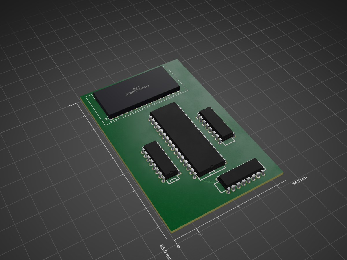
 ashllay/romprogrammer1
Open Source Flash/EEPROM programmer
Romprogrammer is an open-source printed circuit board by ashllay, from the ashllay/romprogrammer repository on GitHub. It is a 2-layer board with 5 parts on 57 nets, routed with 233 tracks and 0 vias.
It is built around the 74HC595. It belongs with the interfaces and adapters boards and the AVR (ATmega, ATtiny) boards of this library.
Open Source Flash/EEPROM programmer
This is an open source programmer for 8 bit-wide parallel Flash/EEPROM chips. So far I've only tested it with (and hardcoded the software for) 2MBit (256Kx8) JEDEC compatible Flash chips (and designed the board layout accordingly).
Larger ROMs would require a redesign of the board, smaller ROMs require an adapter for the pinout.
The board uses an Arduino Nano onto which the firmware is flashed. Then you can read and write your PROMs using the command line tool (which should work on all POSIX systems, but I only tested on Debian Linux).
The board layout is single sided and uses relatively wide clearances and traces - ideal for DIY etching :)
Schematic and layout were made in KiCad EDA. You can use that to export to Gerber or PDF, whatever you prefer for you etching (or what you need for your professional board manufacturing service).
The hardware is designed to be easily DIY etched. It only uses a single layer (+ a few jumper wires). The jumper wires are indicated on the front copper layer. You should also add a 100nF ceramic cap between pins 16 and 32 of the ROM socket to stabilize its power supply.
The software is split into two parts, the firmware for the ATMega328P (the µC on the Arduino Nano) and the Linux command line tool.
The firmware requires gcc-avr and avr-libc. The Makefile also contains a rule for writing the firmware to the Arduino using avrdude. (Using an AVRISPmk2, if you want to use the built-in bootloader of the Arduino, you'll have to adapt the Makefile accordingly).
Just build the software in the firmware directory using make, flash it using make flash.
The Linux command line tool is compiled using CMake, goto the cli directory, create a build directory, cd into it, run cmake, then make:
mkdir build
cd build
cmake ..
makeThe command line interface is relatively easy to use, because it doesn't offer many functions (yet). A first check if building has worked and communication between the host and the programmer is working, can be performed by using the ping command:
romprg /dev/ttyUSB0 ping(You'll require read/write access to the USB serial port, usually by adding your user account to the dialout group).
This should tell you some information about the firmware and indicate that communication is working.
Next, you should verify that your PROM chip is detected correctly by using the id command:
romprg /dev/ttyUSB0 idThis will use the JEDEC identification system to query the vendor and device ID of your ROM chip, like this:
EEPROM chip identification: manufacturer=0xBF, device=0xB6These should match the IDs noted in your EEPROM's device datasheet.
You can erase the whole chip or individual sectors using the erase command:
romprg /dev/ttyUSB0 erase chipto erase the whole chip, or
romprg /dev/ttyUSB0 erase <startaddr> <endaddr>to erase individual sectors. Note that the software only supports 4KByte sectors right now (the most common sector size in Flash chips). endaddr must be the address of the byte after the last byte to be erased. startaddr and endaddr must be sector aligned.
After erasing, you can write data to the chip by using the write command:
romprg /dev/ttyUSB0 write <startaddr> <inputfile>At the moment only flat binary files are supported (i.e. the file content will be written verbatim to the flash). startaddr need not be sector aligned. startaddr + the size of inputfile must be smaller than the chip size.
You may also read back data on the chip using the read command:
romprg /dev/ttyUSB0 read <startaddr> <endaddr> <outfile>endaddr must be greater than startaddr and indicates the address of the byte after the last one to be read. At the moment only flat binary files are supported, i.e. the ROM content will be copied verbatim into outfile. outfile will also be overwritten without asking you for permission, so make sure you know what you're doing ;-)
There are two way to verify the contents of the ROM: the verify command, which reads a section of the ROM and compares it to an input file, and the crc command, which returns the CRC16 of a given ROM section.
romprg /dev/ttyUSB0 verify <startaddr> <endaddr> <infile>Arguments are the same as for the read command (except the file is read instead of written).
romprg /dev/ttyUSB0 crc <startaddr> <endaddr>Here, startaddr and endaddr work the same way as in the other commands.
Copyright (c) 2017 Florian Keßeler
The whole software and hardware is released under the terms of the GNU General Public License version 2.
| Qty | Value | Footprint | References |
|---|---|---|---|
| 3 | 74HC595 | dip_sockets:DIP-16__300 | U2, U3, U4 |
| 1 | ARDUINO_NANO_V3 | arduinonano:ARDUINO_NANO_V3 | U1 |
| 1 | SST39SF020 | dip_sockets:DIP-32__600 | U5 |
5 parts, built around the 74HC595. The full list of its parts is on this page, with links to each part's symbol and footprint where PCBKit's library has them.
From the ashllay/romprogrammer repository on GitHub, at the commit this page was made from: the board is board/romprogrammer.kicad_pcb. PCBKit opens the board in the browser, with nothing to install.
Its repository states no licence, so its author keeps all rights: ask ashllay before reusing the design.
tardate/LittleArduinoProjects
a collection of "Little Electronic & Arduino Projects", most involving electronics or an Arduino in one way or another!

ChrisChrisLoLo/beyblock20
The magnetic, modular, 20-key macropad that can join together to form an ortholinear board

slu4coder/Minimal-64x4-Home-Computer
My DIY TTL home computer with VGA and PS/2 and 4x the processing power of a Commodore C64 or Apple II.

electroniceel/protoboard
Advanced protoboard layout with 1.27mm pitch for smd parts

TobleMiner/DC-UPS
A small DC UPS, designed to keep small appliances like consumer network equipment running during power outages


