Skip to the content
PCBKitNew board
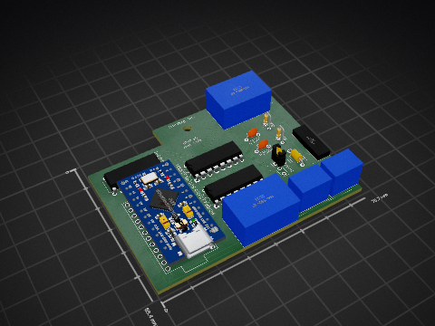
2 layers40 × 36.5 mmMotor driver, the printed circuit board in 3D

Schematic and PCB design of motor driver

Size
40 × 36.5 mm
Copper layers
2
Thickness
1.6 mm
Parts
9
Nets
12
Pads
34
Tracks, vias
84, 0
Routed
Yes
KiCad
KiCad 9.0 (file 20241229)
Created
28 Apr 2025
Updated
28 Apr 2025

Overview

Motor driver is an open-source printed circuit board by Arpitha237, from the Arpitha237/motor-driver repository on GitHub. It is a 2-layer board of 40 × 36.5 mm with 9 parts on 12 nets, routed with 84 tracks and 0 vias.

It is built around the L293D and L7805. Its parts include 4 connectors, 2 ICs, 1 resistor and 1 diode. It belongs with the robots and motor control boards of this library.

Main components

2

README

README.md

Dual DC Motor Driver (L293D)

Controls two DC motors independently (direction & enable) using an L293D driver IC and a 5V regulated supply.

Screenshot 2025-04-28 144846

Screenshot 2025-04-28 153704

Screenshot 2025-04-28 151200

Components:

  • U1 (L293D): Dual H-bridge motor driver IC. This chip contains two independent H-bridge circuits, allowing control of the direction and current flow to two DC motors.
  • U2 (L7805): 5V voltage regulator. This component takes a higher DC input voltage and provides a stable 5V output to power the L293D's logic and the indicator LED.
  • D1 (LED): Light Emitting Diode. This visual indicator illuminates when the circuit has a stable 5V power supply.
  • R1 (Resistor): Current-limiting resistor. This resistor is placed in series with the LED to prevent excessive current flow and potential damage to the LED.
  • J1 (Screw Terminal): Input connector for the external DC power supply. This is where you connect your power source.
  • J2 (Header): Connector for control input signals. This header receives signals (typically from a microcontroller) to control the enable and direction of both motors.
  • J3 (Header): Connector for the first DC motor. Connect the two terminals of your first motor here.
  • J4 (Header): Connector for the second DC motor. Connect the two terminals of your second motor here.

Working:

  1. Power Input: External DC power is connected to the J1 screw terminal. Ensure correct polarity.
  2. Voltage Regulation: The L7805 (U2) steps down and stabilizes the input voltage to a consistent 5V, which is crucial for the proper operation of the L293D and other components.
  3. Power Indication: When the 5V regulation is successful, the LED (D1) lights up, indicating that the circuit is powered and ready for motor control.
  4. Motor Enabling: To allow a motor to run, a HIGH logic signal (+5V) must be applied to the corresponding enable pin on the J2 header (connected to the EN pins of U1). A LOW signal (0V) on the enable pin will stop the motor.
  5. Direction Control: The direction of rotation for each motor is determined by the logic levels applied to the respective direction control pins on the J2 header (connected to the input pins of U1, like 1A, 2A, 3A, 4A). Specific HIGH/LOW combinations on these pins dictate the polarity of the voltage applied across the motor terminals. Consult the L293D datasheet for the exact logic table.
  6. Motor Driving: Based on the enable and direction signals received from J2, the L293D (U1) activates its internal H-bridge circuitry to control the flow of current through the motors connected to J3 and J4, causing them to rotate in the desired direction or stop.

Usage:

  1. Connect your external DC power supply to the J1 screw terminal, paying attention to the positive and negative connections.
  2. Connect your two DC motors to the J3 and J4 headers. The initial direction of rotation might depend on the polarity of the motor connections.
  3. Connect the control output pins of your microcontroller or other control system to the J2 header. Ensure your control signals match the logic levels required by the L293D (typically 0V for LOW and 5V for HIGH).
  4. Control the operation of the motors by manipulating the digital signals sent to the enable and direction control pins on the J2 header. Refer to the L293D datasheet for the specific input logic required to achieve forward, reverse, and brake/coast states for each motor.

Parts

9
QtyValueFootprintReferences
1Conn_01x04_PinConnector:FanPinHeader_1x04_P2.54mm_VerticalJ2
1L293DPackage_DIP:DIP-16_W7.62mmU1
1L7805Package_TO_SOT_THT:TO-220-3_VerticalU2
1LEDLED_THT:LED_D3.0mmD1
1LOGOLOGOG***
1RResistor_THT:R_Axial_DIN0204_L3.6mm_D1.6mm_P7.62mm_HorizontalR1
1Screw_Terminal_01x02TerminalBlock_Phoenix:TerminalBlock_Phoenix_MKDS-1,5-2-5.08_1x02_P5.08mm_HorizontalJ1
1motor 1TerminalBlock_Phoenix:TerminalBlock_Phoenix_MKDS-1,5-2-5.08_1x02_P5.08mm_HorizontalJ3
1motor 2TerminalBlock_Phoenix:TerminalBlock_Phoenix_MKDS-1,5-2-5.08_1x02_P5.08mm_HorizontalJ4

Questions

How big is the Motor driver PCB?

It measures 40 × 36.5 mm and has 2 copper layers, 1.6 mm thick.

What parts does the Motor driver use?

9 parts, built around the L293D and L7805. The full list of its parts is on this page, with links to each part's symbol and footprint where PCBKit's library has them.

Where can I download the Motor driver KiCad files?

From the Arpitha237/motor-driver repository on GitHub, at the commit this page was made from: the board is motor_driver.kicad_pcb and its schematic motor_driver.kicad_sch. PCBKit opens the board in the browser, with nothing to install.

Can I use the Motor driver design in my own project?

Its repository states no licence, so its author keeps all rights: ask Arpitha237 before reusing the design.

Similar boards

  • 2 layers100 × 100 mmFlipdot H Bridge, the printed circuit board in 3D

    Flipdot H Bridge

    comakingspace/FlipDotDisplay

    They were bought at the Makerfaire Hannover 2016.

    76 parts3
  • 2 layers136.5 × 185 mmFaduino-1, the printed circuit board in 3D

    Faduino-1

    silveirago/Kicad-Gustavo

    My Kicad libs

    102 parts3
  • 2 layers72.2 × 53.6 mmLow cost robotics, the printed circuit board in 3D

    Low cost robotics

    gabs911/low_cost_robotics

    Low cost robotics platform for STEM programs.

    19 parts2MIT
  • 2 layers76.2 × 94 mmSumo, the printed circuit board in 3D

    Sumo

    Yourself1011/sumo-bot

    The code for Li Feng Yin and Daniel Zhang's sumo robot, for TEJ3MI

    57 parts2
  • 2 layers30.7 × 57.8 mmOpenturret hat, the printed circuit board in 3D

    Openturret hat

    mrpossoms/openturret

    Opensource designs and software for autonomously aiming gimble

    8 parts1
  • 2 layers73.9 × 42.4 mmSumobot, the printed circuit board in 3D

    Sumobot

    personion222/sumo-robot

    TEJ3MI Final Sumo Wrestling Robot Project Files

    43 parts1
  • 2 layers75.7 × 59.4 mmBbot pcb, the printed circuit board in 3D

    Bbot pcb

    SharpCoder/bbot

    balancing robot

    16 parts1MIT