2 layers83 × 32.8 mm

 AronASzucs/Avalanche323
Handheld ESP32-S3 Geiger counter with a firmware-regulated 400 V boost, SBM-20 tube, USB-C charging and OLED display.
ESP32-Geiger Counter is an open-source printed circuit board by AronASzucs, from the AronASzucs/Avalanche32 repository on GitHub. It is a 2-layer board of 137 × 84 mm with 89 parts on 80 nets, routed with 398 tracks and 614 vias.
It is built around the ESP32-S3-WROOM-1-N8, AP63203WU and UCC27517DBVR-TP, with the BQ25886RGE, USBLC6-2SC6 and AO3401A among its other parts. Its parts include 28 resistors, 26 capacitors, 6 ICs, 6 diodes and 4 transistors. It belongs with the sensors and measurement and lEDs and displays boards and the ESP32 boards of this library.


A handheld, battery-powered Geiger counter built around the ESP32-S3-WROOM-1 and a Soviet SBM-20 Geiger–Müller tube. It has a firmware-regulated 400 V supply, an audible click for each count, a 2.42" OLED display, and a single USB-C port for both charging and programming.
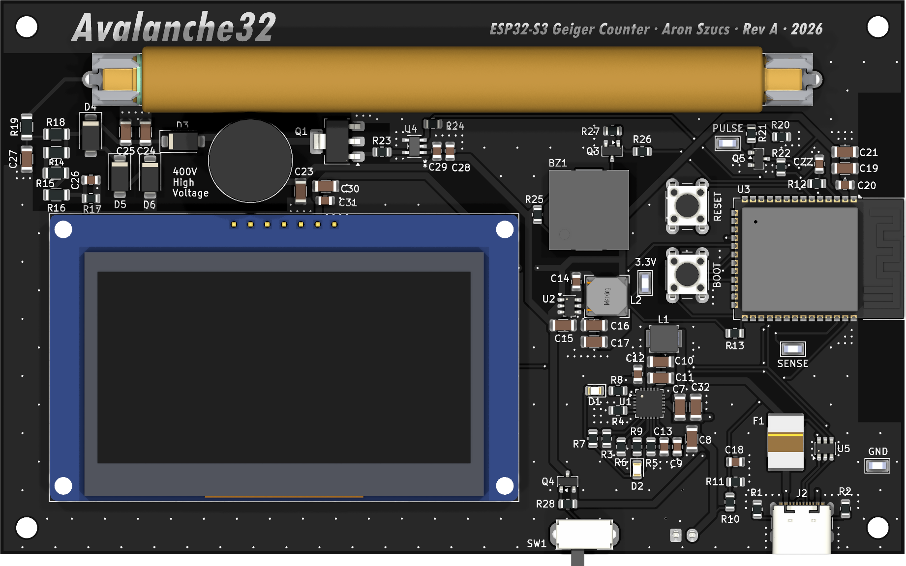
Status: Rev A, in progress. The perfboard prototype is working: it regulates the tube supply at 370–400 V, counts background radiation, and clearly detects real radioactive sources (see Measurements). The Rev A schematic and PCB layout are complete, and the boards and parts have been ordered. Assembly and testing are next.
| Front | Back |
|---|---|
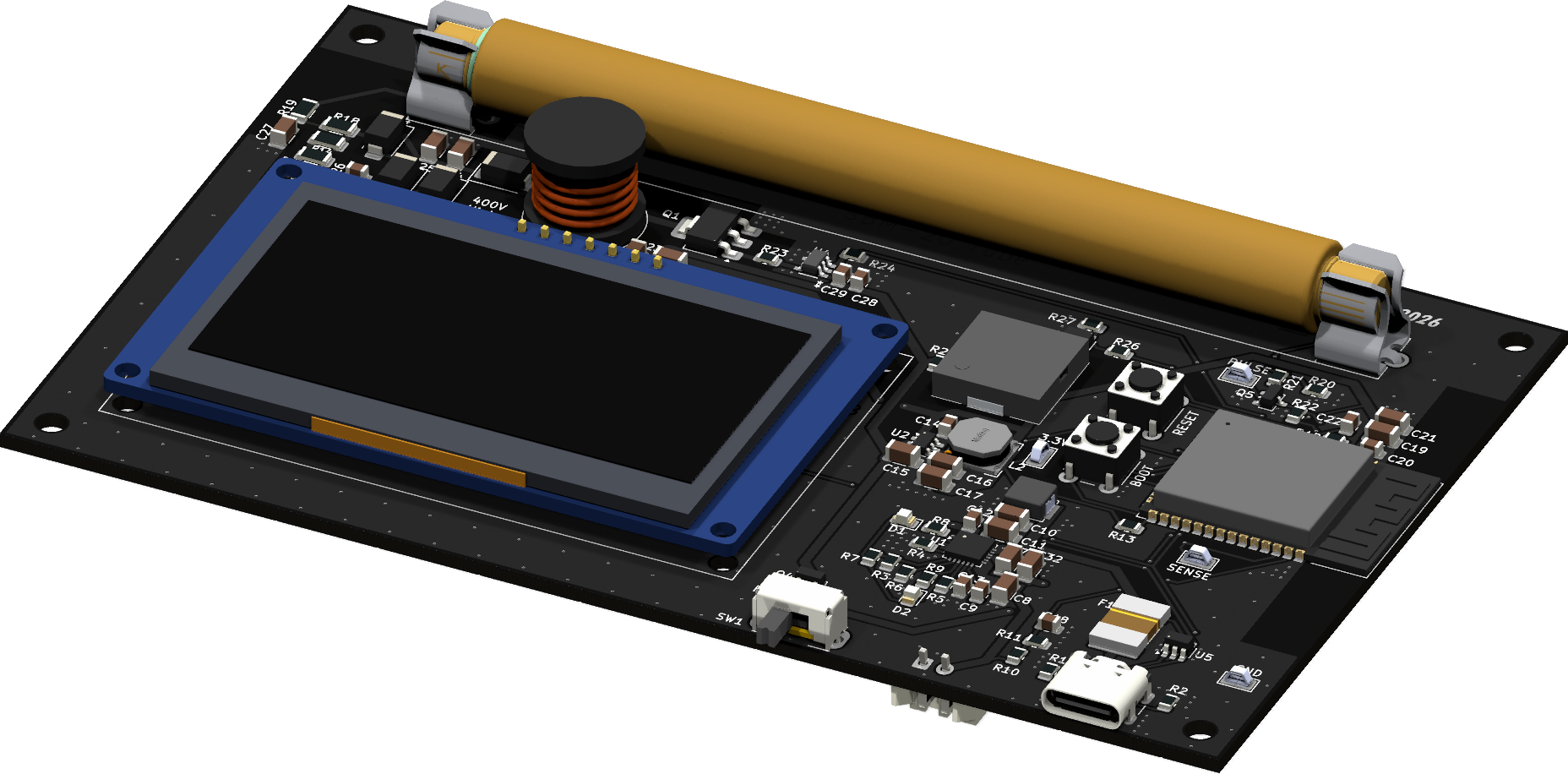 | 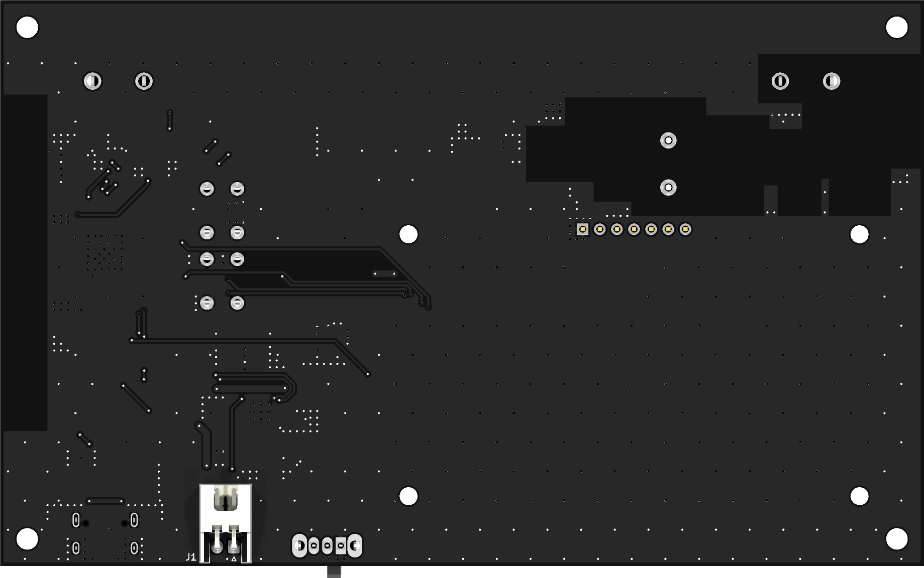 |
| Block | Implementation |
|---|---|
| MCU | ESP32-S3-WROOM-1, native USB (no USB-UART bridge), BOOT and RESET buttons |
| Battery | 2S Li-ion / LiPo pack (7.4 V nominal, 6.0–8.4 V) on a JST-XH connector |
| Charger | TI BQ25886 2-cell boost charger with power-path management, charge-status and power-good LEDs |
| USB-C | 5 V input (5.1 kΩ CC pull-downs, no USB PD), 3 A polyfuse on VBUS, USBLC6-2 ESD protection on the data lines |
| Power switch | Slide switch driving an AO3401A P-FET load switch. The charger stays active, so the pack charges with the unit switched off. |
| 3.3 V rail | Diodes AP63203 synchronous buck converter |
| High voltage | Firmware-regulated boost from the system rail to ~400 V (details below) |
| Detection | SBM-20 cathode pulse → MMBT3904 pulse shaper → ESP32 interrupt |
| Audio | Piezo transducer switched by a 2N7002 low-side MOSFET, one click per count |
| Display | 2.42" 128×64 SSD1309 OLED module over SPI |
| Battery monitor | 1 MΩ / 330 kΩ divider into an ESP32 ADC input |
| Signal | ESP32-S3 GPIO |
|---|---|
| HV_PWM (gate driver input) | IO4 |
| HV_SENSE (HV divider, ADC1) | IO2 |
| PULSE (tube pulse, active low) | IO5 |
| PIEZO | IO6 |
| VBAT_SENSE (ADC1) | IO1 |
| OLED SCK / MOSI / CS / DC / RST | IO12 / IO11 / IO10 / IO13 / IO21 |
| USB D− / D+ | IO19 / IO20 |
Test points are provided for 3.3 V, GND, PULSE and HV_SENSE.
| Parameter | Value |
|---|---|
| Dimensions | 137 × 84 mm |
| Layers | 2 (1.6 mm FR-4, 1 oz copper) |
| Finish | Black solder mask, white silkscreen, HASL |
| Mounting | 4 × M3 mounting holes |
These readings are from the perfboard prototype, with each sample placed directly against the SBM-20 tube. Dose rates use the firmware's conversion factor of 0.0057 µSv/h per CPM (SBM-20, Cs-137 basis), so they are indicative only.
| Source | CPM | × Background | Indicated µSv/h |
|---|---|---|---|
| Normal indoor background | 15–25 | 1× | ~0.09–0.14 |
| Uranium glass plate | 300–400 | ~17× | ~1.7–2.3 |
| Vintage radium-dial watch | 350–450 | ~20× | ~2.0–2.6 |
| Watch + plate together | 550–650 | ~30× | ~3.1–3.7 |
| Fiestaware red-orange saucer (uranium glaze) | ~8,700 | ~435× | ~50 |
| Fiestaware cup resting on saucer | ~13,400 | ~670× | ~76 |
Contact readings on glazed ceramics are mostly beta from the uranium decay chain, so the µSv/h values overstate the actual dose.
The current SBM-20 is degraded and sometimes fires a burst of 100–1000+ pulses instead of a single one. The firmware works around this with a burst filter (BURST_FILTER) that merges each burst into one count, at the cost of undercounting at very high rates. A replacement tube is on the way.
Firmware/HV_Test/HV_Test.ino is a bench test for the HV supply and counting chain, written for the Arduino ESP32 core. It provides:
Note: this sketch targets the perfboard prototype, which uses a classic ESP32 dev board. Its pin assignments (IO4, IO35, IO27, IO25) do not match the Rev A PCB. Update the constants at the top of the file using the GPIO map before running it on the PCB.
| Path | Contents |
|---|---|
ESP32-Geiger-Counter.kicad_* | KiCad project: schematic, PCB and design rules |
Custom Parts.kicad_sym, libs/ | Custom symbols, footprints and 3D models |
production/ | JLCPCB fabrication outputs: Gerber/drill archive, BOM, pick-and-place and IPC netlist |
bom/ibom.html | Interactive BOM for hand assembly |
Images/ | 3D renders (3D/) and per-layer plots (Layers/) |
scripts/generate_images.py | Regenerates everything in Images/ using kicad-cli |
Firmware/ | ESP32 firmware |
Draft1.asc | LTspice simulation of the HV boost |
To regenerate the images (requires KiCad 9+ and, for PNG layer plots, pip install pymupdf):
python scripts/generate_images.pyKiCad · LTspice · Arduino (ESP32 core) · C++
This device generates ~400 V DC. The stored energy is small, but do not touch the HV section while the unit is powered. Before handling the board, let the capacitors discharge: wait for the HV reading to fall to 0 V.
Store radioactive test samples (radium dials, uranium glass, uranium-glazed ceramics) sealed and away from living spaces. Never open radium-dial watches or gauges, and never eat or drink from uranium-glazed dishware.
| Qty | Value | Footprint | References |
|---|---|---|---|
| 5 | 100nF | Capacitor_SMD:C_0805_2012Metric | C14, C18, C20, C29, C31 |
| 5 | 10uF | Capacitor_SMD:C_1206_3216Metric | C8, C11, C15, C19, C30 |
| 5 | 22uF | Capacitor_SMD:C_1206_3216Metric | C7, C10, C16, C17, C32 |
| 4 | 10K | Resistor_SMD:R_0805_2012Metric | R3, R7, R12, R13 |
| 4 | MountingHole | MountingHole:MountingHole_3.2mm_M3 | H1, H2, H3, H4 |
| 3 | 100M | Resistor_SMD:R_1206_3216Metric | R14, R15, R16 |
| 3 | 100k | Resistor_SMD:R_0805_2012Metric | R20, R27, R28 |
| 3 | 10k | Resistor_SMD:R_0805_2012Metric | R21, R22, R24 |
| 3 | 10nF 1kV | Capacitor_SMD:C_1206_3216Metric | C24, C25, C27 |
| 3 | 150V Zener | Diode_SMD:D_SMA | D4, D5, D6 |
| 3 | 1uF | Capacitor_SMD:C_0805_2012Metric | C12, C22, C28 |
| 2 | 1k | Resistor_SMD:R_0805_2012Metric | R25, R26 |
| 2 | 2.2K | Resistor_SMD:R_0805_2012Metric | R8, R9 |
| 2 | 5.1K | Resistor_SMD:R_0805_2012Metric | R1, R2 |
| 2 | LED | LED_SMD:LED_0805_2012Metric | D1, D2 |
| 1 | 10 | Resistor_SMD:R_0805_2012Metric | R23 |
| 1 | 10mH | Inductor_THT:L_Radial_D12.5mm_P7.00mm_Fastron_09HCP | L3 |
| 1 | 10uF 25V | Capacitor_SMD:C_1206_3216Metric | C23 |
| 1 | 1M | Resistor_SMD:R_0805_2012Metric | R10 |
| 1 | 1M | Resistor_SMD:R_1206_3216Metric | R18 |
| 1 | 1uH | SRP4020TA-1R0M:IND_SRP4020TA-1R0M | L1 |
| 1 | 2.2nF | Capacitor_SMD:C_0805_2012Metric | C26 |
| 1 | 200K | Resistor_SMD:R_0805_2012Metric | R4 |
| 1 | 2N7002 | Package_TO_SOT_SMD:SOT-23 | Q3 |
| 1 | 2s1p Lipo Battery Pack (8.4V-6V) | Connector_JST:JST_XH_S2B-XH-A_1x02_P2.50mm_Horizontal | J1 |
| 1 | 3.3V | TestPoint:TestPoint_Keystone_5015_Micro_Mini | 3.3V |
| 1 | 3.83k | Resistor_SMD:R_0805_2012Metric | R5 |
| 1 | 3.9uH | Inductor_SMD:L_Bourns-SRN6028 | L2 |
| 1 | 330k | Resistor_SMD:R_0805_2012Metric | R11 |
| 1 | 383 | Resistor_SMD:R_0805_2012Metric | R6 |
| 1 | 3A Polyfuse | Fuse:Fuse_2920_7451Metric | F1 |
| 1 | 4.7uF | Capacitor_SMD:C_0805_2012Metric | C13 |
| 1 | 47nF | Capacitor_SMD:C_0805_2012Metric | C9 |
| 1 | 47uF | Capacitor_SMD:C_1206_3216Metric | C21 |
| 1 | 5.1M | Resistor_SMD:R_1206_3216Metric | R19 |
| 1 | 680k | Resistor_SMD:R_0805_2012Metric | R17 |
| 1 | AO3401A | Package_TO_SOT_SMD:SOT-23 | Q4 |
| 1 | AP63203WU | Package_TO_SOT_SMD:TSOT-23-6 | U2 |
| 1 | BOOT | Button_Switch_THT:SW_PUSH_6mm | BOOT |
| 1 | BQ25886RGE | Package_DFN_QFN:Texas_RGE0024H_VQFN-24-1EP_4x4mm_P0.5mm_EP2.7x2.7mm_ThermalVias | U1 |
| 1 | Buzzer | CPT_1203_78_SMT_TR:XDCR_CPT-1203-78-SMT-TR | BZ1 |
| 1 | Conn_01x07 | footprints:OLED_2.42in_SSD1309_SPI_7pin | J5 |
| 1 | ESP32-S3-WROOM-1 | RF_Module:ESP32-S3-WROOM-1 | U3 |
| 1 | GND | TestPoint:TestPoint_Keystone_5015_Micro_Mini | GND |
| 1 | HV_SENSE | TestPoint:TestPoint_Keystone_5015_Micro_Mini | SENSE |
| 1 | MMBT3904 | Package_TO_SOT_SMD:SOT-23 | Q5 |
| 1 | PULSE | TestPoint:TestPoint_Keystone_5015_Micro_Mini | PULSE |
| 1 | RESET | Button_Switch_THT:SW_PUSH_6mm | RESET |
| 1 | SBM-20 Geiger Mueller Tube | 3529:SBM-20 Tube | U6 |
| 1 | STN1HNK60 | Package_TO_SOT_SMD:SOT-223-3_TabPin2 | Q1 |
| 1 | SW_SPDT | Button_Switch_THT:SW_Slide_SPDT_Angled_CK_OS102011MA1Q | SW1 |
| 1 | UCC27517DBVR | UCC27517:DBV5_TEX | U4 |
| 1 | US1M | Diode_SMD:D_SMA | D3 |
| 1 | USBLC6-2SC6 | Package_TO_SOT_SMD:SOT-23-6 | U5 |
| 1 | USB_C_Receptacle_USB2.0_16P | Connector_USB:USB_C_Receptacle_GCT_USB4105-xx-A_16P_TopMnt_Horizontal | J2 |

N-Pulse/EEG-HW-System
EEG acquisition board, power board and headset development


ryandrake08/billy
Offline Big Mouth Billy Bass voice jokester powered by an ESP32-S3 and a local GPU backend.

atomicra1n/wifi-geiger-counter
A DIY Geiger counter PCB which can detect ionizing radiation and log readings over Wi-Fi. Built with an ESP32, and a HV multiplier circuit that steps up 3.7V to 400V for the GM tube.


N-Pulse/BMI-EMG-HW
Find the schematics and PCB layout for the hardware of the EMG Bracelet

proveskit/antenna-board
The PROVES Kit Antenna Boards! By convention the Z+ Top Cap of the satellite.
It measures 137 × 84 mm and has 2 copper layers, 1.6 mm thick.
89 parts, built around the ESP32-S3-WROOM-1-N8, AP63203WU, UCC27517DBVR-TP and BQ25886RGE. The full list of its parts is on this page, with links to each part's symbol and footprint where PCBKit's library has them.
From the AronASzucs/Avalanche32 repository on GitHub, at the commit this page was made from: the board is ESP32-Geiger-Counter.kicad_pcb and its schematic ESP32-Geiger-Counter.kicad_sch. PCBKit opens the board in the browser, with nothing to install.
Its repository states no licence, so its author keeps all rights: ask AronASzucs before reusing the design.