2 layers
Unity gain opamp
N-Pulse/EEG-HW-System
EEG acquisition board, power board and headset development
15 parts
 N-Pulse/EEG-HW-System
EEG acquisition board, power board and headset development
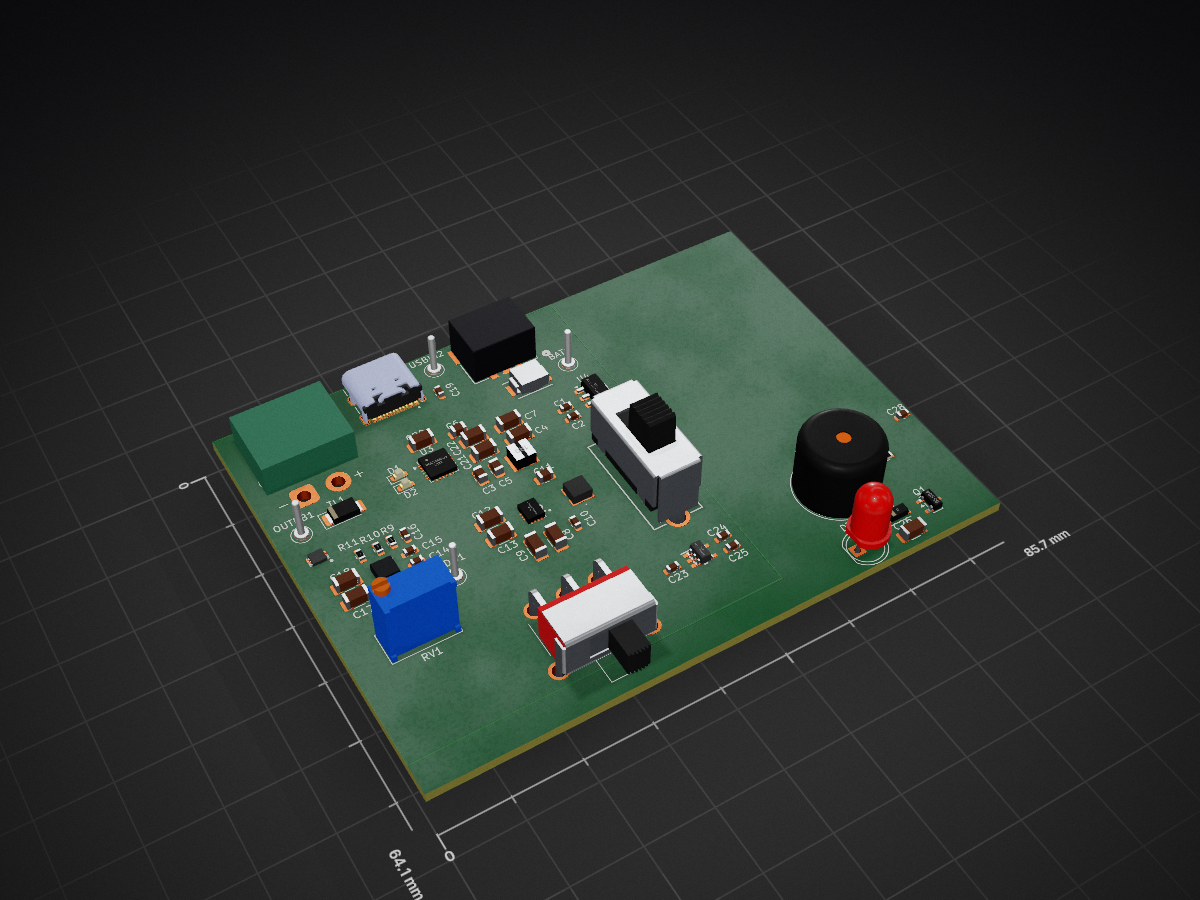
Power board v1 is an open-source printed circuit board by N-Pulse, from the N-Pulse/EEG-HW-System repository on GitHub. It is a 4-layer board with 79 parts on 55 nets.
It is built around the TPS63070RNMR, BQ25886RGE and USBLC6-2SC6, with the 5MS1S102AM6QES, BSS84 and MFS201N-9-Z among its other parts. Its parts include 27 capacitors, 24 resistors, 6 ICs, 4 diodes and 3 connectors.


A teaching board for the N-Pulse electronics workshop: an ESP32-S3 platform with a complete battery power path, four sensors, and a heart-rate (PPG) front end — designed so that new members can learn hardware design by reading a real, working board rather than a toy example.

Most beginner projects are one circuit. This board is deliberately the opposite: it puts one worked example of nearly every subsystem you meet in real hardware onto a single PCB, so that "how do I charge a battery?", "how do I protect a USB port?" or "how do I amplify a microvolt sensor?" all have an answer you can hold in your hand and probe with a scope.
It is a reference, not a first project. Read it, measure it, copy from it.
Every design decision is documented in DESIGN_NOTES.md, which also contains general guidance on how to draw a good schematic and how to lay out a good PCB.
Power
+3V3_ESP32 (always on) and +3V3 (switched)Sensing
Interfaces
Physical: 70 × 80 mm, 2-layer, 142 components, four M4 mounting holes.
Powering it. Plug in USB-C and it runs, regardless of the ON/OFF switch. On
battery, slide the ON/OFF switch (bottom edge, marked ON/OFF). With USB
connected the board runs from USB and charges the cell at the same time.
Charging. The three LEDs on the left edge are, top to bottom, CHRG
(charging), DONE (complete) and PG (USB power good).
Programming. Connect USB-C — the board enumerates directly as an ESP32-S3.
Normally you can just flash it. If you need to force download mode: slide the
BOOT0 switch (right edge) to the boot position, press ENABLE to reset, flash,
then slide it back and reset again. The LED beside the switch shows its position.
Reading your pulse. Rest a fingertip on the fingerprint symbol in the middle of the board, covering the LED and photodiode, with light steady pressure. The amplifier needs a second or two to settle. Signal quality depends a lot on contact pressure and ambient light — that is part of what makes it a good teaching circuit.
I²C expansion. The 4-pin header on the right edge is 3V3 / SDA / SCL / GND
(labelled on the silkscreen). It is ESD-protected and shares the bus with the
on-board sensors, so remember the address space is shared.
Test points. Every rail and every interesting node is brought out:
+5V USB, 3V3 USB, 3V3 BATT, 3V3 ESP32, 3V3, +BATT, -BATT, GND,
plus FB, PR1, MODE and PWR SW for the power circuits.
Built with KiCad 9/10. Clone and open Electronics_Workwhop_PCB.kicad_pro.
All custom symbols and footprints live in the repository — N_pulse.pretty/ for
footprints and Library/ for vendor symbol libraries — so the project should
open with no missing parts. Nothing needs to be installed globally.
Electronics_Workwhop_PCB.kicad_pro   project file — open this
├── Architecture.kicad_sch           top-level sheet
├── ESP32.kicad_sch                  MCU, SD card, LEDs, buzzer, buttons
├── Power_management.kicad_sch       USB-C, charger, protection, regulators
├── Sensors.kicad_sch                SHT40, accelerometer, temperature, PPG
└── Electronics_Workwhop_PCB.kicad_pcb
DESIGN_NOTES.md                      why the circuits look the way they do
docs/ images and documentation assetsSee Appendix A of DESIGN_NOTES.md for the full table, generated from the netlist.
The one rule worth memorising: analog inputs must be on ADC1 (IO1–IO10). ADC2 cannot be read while Wi-Fi is running.
KiCad files cannot be merged. If two people edit the same sheet at the same time, git produces a conflict that no one can resolve by hand.
Before you start work, say which sheet you are taking, and pull before you open the project. Commit with a message describing the change, not just "update".
The pre-fabrication checklist in Appendix B of DESIGN_NOTES.md should be run before any board is ordered.
"What I cannot create, I do not understand." — Richard Feynman
(also printed on the board)
| Qty | Value | Footprint | References |
|---|---|---|---|
| 7 | 100nF | Capacitor_SMD:C_0603_1608Metric | C10, C14, C19, C23, C24, C25, C28 |
| 6 | 22uF | Capacitor_SMD:C_1206_3216Metric | C8, C9, C12, C13, C17, C18 |
| 3 | 10k | Resistor_SMD:R_0603_1608Metric | R1, R19, R20 |
| 3 | 2.2k | Resistor_SMD:R_0603_1608Metric | R3, R4, R24 |
| 3 | 22u | Capacitor_SMD:C_1206_3216Metric | C4, C21, C22 |
| 2 | 100kOhm | Resistor_SMD:R_0603_1608Metric | R7, R8 |
| 2 | 10u | Capacitor_SMD:C_0805_2012Metric | C5, C6 |
| 2 | 1uF | Capacitor_SMD:C_0603_1608Metric | C1, C2 |
| 2 | 4.7u | Capacitor_SMD:C_1206_3216Metric | C7, C26 |
| 2 | 5.1k | Resistor_SMD:R_0603_1608Metric | R12, R13 |
| 2 | LED_Small | LED_SMD:LED_0603_1608Metric | D1, D2 |
| 2 | TestPoint | TestPoint:TestPoint_Keystone_5000-5004_Miniature | BAT1, USBIN2 |
| 1 | 0-500 | Potentiometer_THT:Potentiometer_Bourns_3296W_Vertical | RV1 |
| 1 | 1.5uH | KiCad induct:78438336015 | LB1 |
| 1 | 10kOhm | Resistor_SMD:R_0603_1608Metric | R5 |
| 1 | 10uF | Capacitor_SMD:C_0805_2012Metric | C11 |
| 1 | 1u | KiCad_L_CHA:INDC3030X200N | L1 |
| 1 | 1u | Capacitor_SMD:C_1206_3216Metric | C20 |
| 1 | 2053380003 | footprints:CONN_2053380000-SD_03_MOL | J3 |
| 1 | 220k | Resistor_SMD:R_0603_1608Metric | R15 |
| 1 | 220nF | Capacitor_SMD:C_0603_1608Metric | C15 |
| 1 | 26.7k | Resistor_SMD:R_0603_1608Metric | R21 |
| 1 | 30.1k | Resistor_SMD:R_0603_1608Metric | R17 |
| 1 | 330 | Resistor_SMD:R_0603_1608Metric | R22 |
| 1 | 383 | Resistor_SMD:R_0603_1608Metric | R16 |
| 1 | 470 | Resistor_SMD:R_0603_1608Metric | R11 |
| 1 | 470k | Resistor_SMD:R_0603_1608Metric | R23 |
| 1 | 470nF | Capacitor_SMD:C_0603_1608Metric | C16 |
| 1 | 47n | Capacitor_SMD:C_0805_2012Metric | C3 |
| 1 | 5.23k | Resistor_SMD:R_0603_1608Metric | R2 |
| 1 | 51.1k | Resistor_SMD:R_0603_1608Metric | R18 |
| 1 | 5MS1S102AM6QES | KiCad_switchP:5MS1S102AM6QES | S2 |
| 1 | 6.2k | Resistor_SMD:R_0603_1608Metric | R14 |
| 1 | 60.4k | Resistor_SMD:R_0603_1608Metric | R9 |
| 1 | 665kOhm | Resistor_SMD:R_0603_1608Metric | R6 |
| 1 | 9.53k | Resistor_SMD:R_0603_1608Metric | R10 |
| 1 | AP2281-1FMG-7 | KiCad_LS:SON50P201X181X60-7N | IC3 |
| 1 | BQ25886RGE | Package_DFN_QFN:Texas_RGE0024H_VQFN-24-1EP_4x4mm_P0.5mm_EP2.7x2.7mm | U3 |
| 1 | BSS84 | Package_TO_SOT_SMD:SOT-23 | Q1 |
| 1 | Buzzer | Buzzer_Beeper:Buzzer_12x9.5RM7.6 | BZ1 |
| 1 | D | Diode_SMD:D_SOD-123 | D4 |
| 1 | D_Zener | SMBJ9.0A:DIOM5436X261N | TB1 |
| 1 | D_Zener | Package_TO_SOT_SMD:SOT-23 | DL1 |
| 1 | LED | LED_THT:LED_D5.0mm | D3 |
| 1 | MCP1703Ax-500xxMB | Package_TO_SOT_SMD:SOT-89-3 | U4 |
| 1 | MCP6541T-I_OT | KiCad COMP:SOT95P270X145-5N | IC1 |
| 1 | MFS201N-9-Z | KiCad switch:MFS201N9Z | S1 |
| 1 | TPS63070RNMR | KiCad TPS63070:TPS630701RNMR | IC2 |
| 1 | TPS7A8101DRBT | Kicad TPS 7A8101:SON65P300X300X100-9N-D | HM1 |
| 1 | UJ20-C-H-G-SMT-1-P16-TR | usbc:SAMESKY_UJ20-C-H-G-SMT-1-P16-TR | J5 |
| 1 | USBLC6-2SC6 | Package_TO_SOT_SMD:SOT-23-6 | U2 |
| 1 | VinLDO | TestPoint:TestPoint_Keystone_5000-5004_Miniature | INLDO1 |
| 1 | VoutPB | TestPoint:TestPoint_Keystone_5000-5004_Miniature | OUTPB1 |
| 1 | XT30F | Connector_AMASS:AMASS_XT30PW-F_1x02_P2.50mm_Horizontal | J2 |
| 1 | ~ | Diode_SMD:D_SOD-128 | TL1 |
N-Pulse/EEG-HW-System
EEG acquisition board, power board and headset development

N-Pulse/BMI-EMG-HW
Find the schematics and PCB layout for the hardware of the EMG Bracelet

AronASzucs/Avalanche32
Handheld ESP32-S3 Geiger counter with a firmware-regulated 400 V boost, SBM-20 tube, USB-C charging and OLED display.

rishivg/IO-SDR
Open-Source software-defined FPGA radio hardware platform


SunnyYoshimitsu/Reconfigurable-Space-Compute-Cluster
Here will be the repository for an "extremely reconfigurable satellite" aimed toward at competing in NASA Minds and hopefully assist Artemis in its missions.


proveskit/antenna-board
The PROVES Kit Antenna Boards! By convention the Z+ Top Cap of the satellite.
79 parts, built around the TPS63070RNMR, BQ25886RGE, USBLC6-2SC6 and 5MS1S102AM6QES. The full list of its parts is on this page, with links to each part's symbol and footprint where PCBKit's library has them.
From the N-Pulse/EEG-HW-System repository on GitHub, at the commit this page was made from: the board is power-board/Power_board_v1.kicad_pcb and its schematic power-board/LDO.kicad_sch. PCBKit opens the board in the browser, with nothing to install.
Its repository states no licence, so its author keeps all rights: ask N-Pulse before reusing the design.