2 layers93.4 × 42.6 mm

 arkandas/esp32-led-controller5
Controller for ws2812b/sk6812 LEDs
Esp32-led controller is an open-source printed circuit board by arkandas, from the arkandas/esp32-led-controller repository on GitHub, published under the MIT licence. It is a 2-layer board of 53.8 × 36.2 mm with 25 parts on 48 nets, routed with 182 tracks and 83 vias.
It is built around the ESP32-S3-WROOM-1-N8, SN74AHCT125PWRE4 and LM1117S-3.3, with the NH-B2020RGBA-HF among its other parts. Its parts include 6 switches, 5 resistors, 4 capacitors, 4 ICs and 3 connectors. It belongs with the ESP32 boards of this library.


A custom ESP32-based controller for WS2812B/SK6812/WS2814 LED strips with web interface and Alexa integration.
Latest Version: V2 includes 24V RGBW support (WS2814), temperature/humidity monitoring, and enhanced status LEDs.
✅ Released - Latest version in main branch
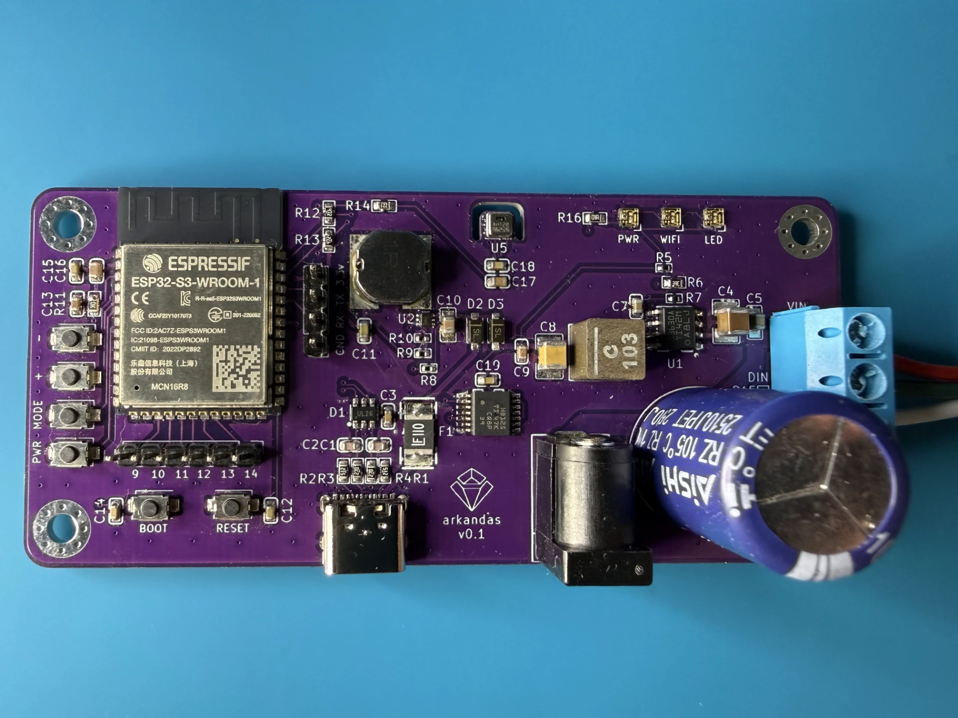
✅ Released - Tagged as v1.0.0
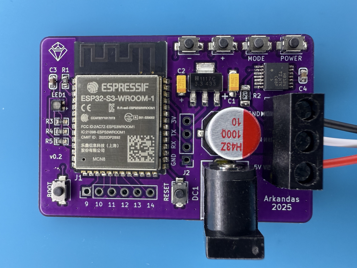
The following documentation applies to Version 2 of the project. All files are located in the v2/ directory.
v2/
├── code/                      # Arduino code & web interface
│   └── esp32-ws2814/          # WS2814 (RGBW) version
│       ├── data/              # Web interface files
│       │   ├── index.html     # Main web UI
│       │   ├── style.css      # Styling
│       │   └── app.js         # JavaScript controls
│       └── esp32-ws2814.ino   # Arduino sketch
├── kicad/                     # KiCad PCB project files
└── assets/ # Board photos & schematicsAdd ESP32 Board Support:
File → Preferences → Additional Board Manager URLs:
https://raw.githubusercontent.com/espressif/arduino-esp32/gh-pages/package_esp32_index.json
Board Configuration:
Install Libraries via Library Manager
Configure Settings in the .ino file:
const char* ssid = "Your_WiFi_Network";
const char* password = "Your_WiFi_Password";
#define DEVICE_NAME "Your_Alexa_Device_Name"
#define WIFI_HOSTNAME "Your_Device_Hostname"
#define WEB_SERVER_PORT 8080  // Your preferred port
#define NUM_LEDS 60  // Your LED count
Upload Web Files:
data folder in your sketch directoryUpload Arduino Sketch normally
The v2 board uses an ESP32-S3 with built-in USB - no need for an external USB-to-serial adapter.
USB Connection:
Arduino IDE USB Configuration:
To get USB UART working on the Serial Monitor:
Board Settings (Tools menu):
ESP32S3 Dev ModuleEnabled ⚠️ Important for Serial MonitorHardware CDC and JTAGUART0 / Hardware CDC8MB8M with spiffs (3MB APP/1.5MB SPIFFS)921600 (or lower if uploads fail)Port Selection:
/dev/cu.usbmodem*COM*/dev/ttyACM*USB CDC On Boot Explained:
Enabled, the Serial Monitor will work over USB immediately after bootSerial.println() without additional hardwareFirst-Time Programming:
BOOT button (if available on your board)BOOT button when upload starts115200 baud to see outputTroubleshooting:
460800 or 115200115200 and USB CDC On Boot is enabled| ESP32 Pin | Connection |
|---|---|
| GPIO 40 | WS2814 LED Strip Data |
| GPIO 41 | Status LEDs (3x SK6805-EC20) |
| GPIO 1 | I2C SCL (AHT20 Sensor) |
| GPIO 2 | I2C SDA (AHT20 Sensor) |
| GPIO 4-7 | Control Buttons |
After successful upload:
http://[ESP32_IP]:[WEB_SERVER_PORT]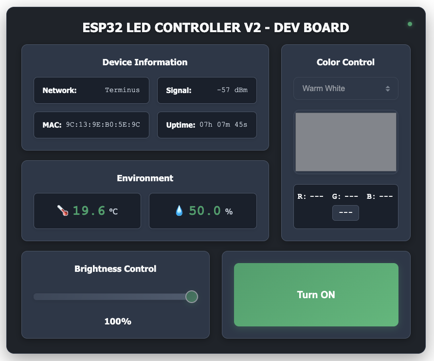
The board features 3 RGB status LEDs:
Custom PCB design includes:
The following documentation applies to Version 1 of the project. All files are located in the v1/ directory.
v1/
├── code/                       # Arduino code & web interface
│   ├── esp32-ws2812b/          # WS2812B (RGB) version
│   │   ├── data/               # Web interface files
│   │   │   ├── index.html      # Main web UI
│   │   │   ├── style.css       # Styling
│   │   │   └── app.js          # JavaScript controls
│   │   └── esp32-ws2812b.ino   # Arduino sketch
│   └── esp32-sk6812/           # SK6812 (RGBW) version
│       ├── data/               # Web interface files
│       └── esp32-sk6812.ino    # Arduino sketch
├── kicad/                      # KiCad PCB project files
├── gerbers/                    # Manufacturing files
├── datasheets/                 # Component datasheets
├── ibom/                       # Interactive BOM
└── assets/ # Board photosAdd ESP32 Board Support:
File → Preferences → Additional Board Manager URLs:
https://raw.githubusercontent.com/espressif/arduino-esp32/gh-pages/package_esp32_index.json
Board Configuration:
Install Libraries via Library Manager
Choose Your LED Type:
v1/code/esp32-ws2812b/ for standard RGB stripsv1/code/esp32-sk6812/ for RGBW strips with dedicated white channelConfigure Settings in the .ino file:
const char* ssid = "Your_WiFi_Network";
const char* password = "Your_WiFi_Password";
#define DEVICE_NAME "Bedroom Lights"
#define NUM_LEDS 60  // Your LED count
Upload Web Files:
data folder in your sketch directoryUpload Arduino Sketch normally
| ESP32 Pin | Connection |
|---|---|
| GPIO 2 | LED Strip Data |
| GPIO 17 | Status LED (Red) |
| GPIO 16 | Status LED (Green) |
| GPIO 18 | Status LED (Blue) |
| GPIO 4-7 | Control Buttons |
After successful upload:
http://[ESP32_IP]:8080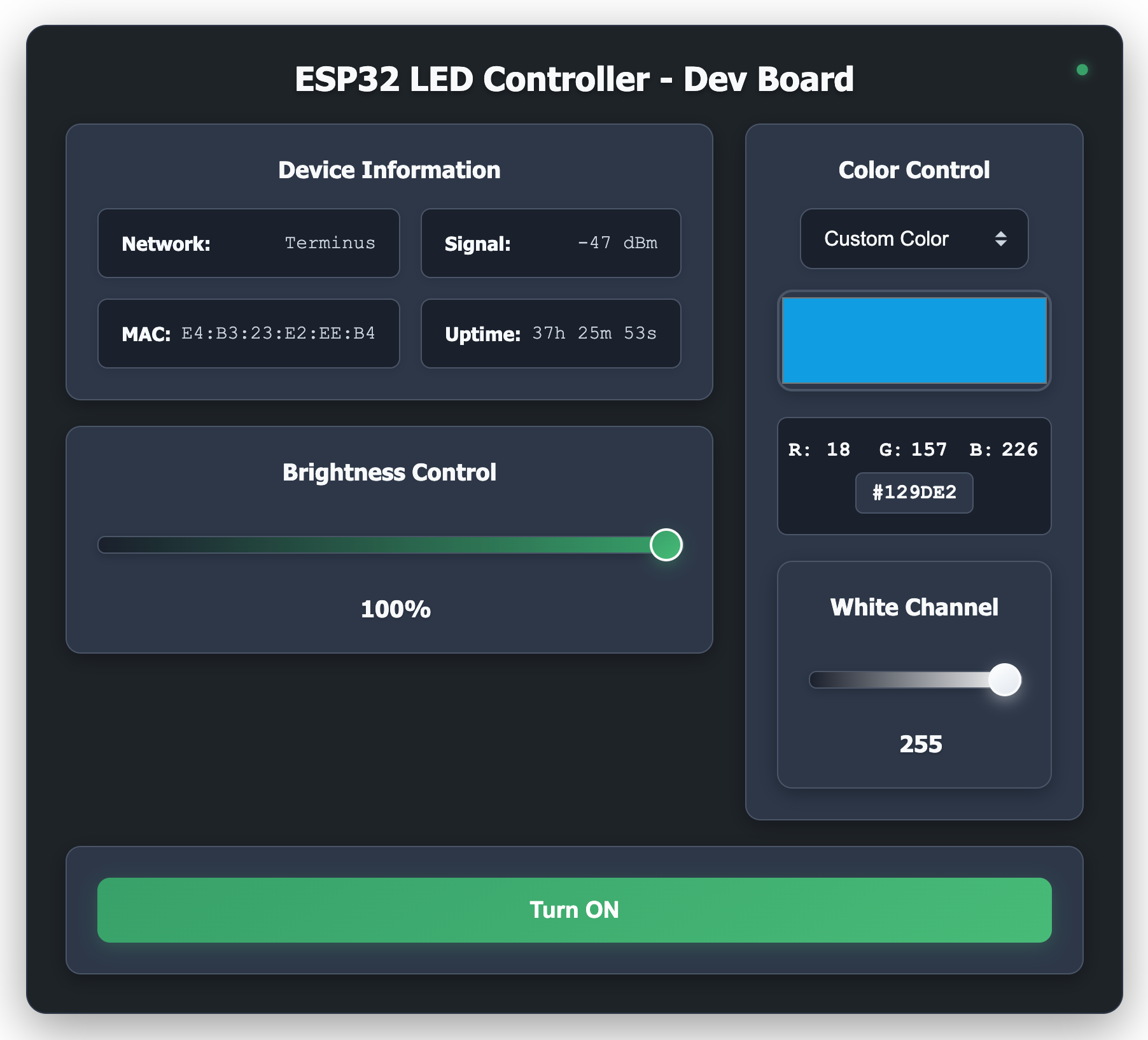
Read the full build story and PCB design process for V1: ESP32 LED Controller
Custom PCB design includes:
The web interface uses vanilla JavaScript with no external dependencies. All files are served from ESP32's LittleFS for fast loading and offline operation.
This project is licensed under the MIT License - see the LICENSE file for details.
| Qty | Value | Footprint | References |
|---|---|---|---|
| 2 | 180R | easyeda2kicad:R0603 | R4, R5 |
| 2 | 1uf | easyeda2kicad:C0603 | C3, C4 |
| 1 | + | easyeda2kicad:SW-SMD_L3.9-W3.0-P4.45 | SW4 |
| 1 | - | easyeda2kicad:SW-SMD_L3.9-W3.0-P4.45 | SW3 |
| 1 | 1000uf | easyeda2kicad:CAP-SMD_BD8.0-L8.3-W8.3-LS9.1-FD | U3 |
| 1 | 10K | easyeda2kicad:R0603 | R1 |
| 1 | 10uf | easyeda2kicad:CAP-SMD_L3.2-W1.6-RD-C7171 | C1 |
| 1 | 120R | easyeda2kicad:R0603 | R3 |
| 1 | 22uf | easyeda2kicad:CASE-A_3216 | C2 |
| 1 | 5V 10A | easyeda2kicad:DC-IN-TH_DC-005-5A-2.5 | DC1 |
| 1 | 62R | Resistor_SMD:R_1206_3216Metric | R2 |
| 1 | BOOT | easyeda2kicad:SW-SMD_L3.9-W3.0-P4.45 | SW1 |
| 1 | ESP32-S3-WROOM-1-N8 | easyeda2kicad:WIFIM-SMD_ESP32-S3-WROOM-1-N8 | U2 |
| 1 | LED_Conn | TerminalBlock:TerminalBlock_MaiXu_MX126-5.0-03P_1x03_P5.00mm | J3 |
| 1 | LM1117S-3.3 | easyeda2kicad:SOT-223-3_L6.5-W3.4-P2.30-LS7.0-BR | U1 |
| 1 | LOGO | logos:logo2 | G*** |
| 1 | MODE | easyeda2kicad:SW-SMD_L3.9-W3.0-P4.45 | SW5 |
| 1 | NH-B2020RGBA-HF | easyeda2kicad:LED-ARRAY-SMD_4P-L2.1-W2.1-TL_NH-B2020RGBA | LED1 |
| 1 | POWER | easyeda2kicad:SW-SMD_L3.9-W3.0-P4.45 | SW6 |
| 1 | Prog | Connector_PinHeader_2.54mm:PinHeader_1x04_P2.54mm_Vertical | J2 |
| 1 | RESET | easyeda2kicad:SW-SMD_L3.9-W3.0-P4.45 | SW2 |
| 1 | SN74AHCT125PWR | easyeda2kicad:TSSOP-14_L5.0-W4.4-P0.65-LS6.4-BL | U4 |
| 1 | header | Connector_PinHeader_2.54mm:PinHeader_1x06_P2.54mm_Vertical | J1 |
It measures 53.8 × 36.2 mm and has 2 copper layers, 1.6 mm thick.
25 parts, built around the ESP32-S3-WROOM-1-N8, SN74AHCT125PWRE4, LM1117S-3.3 and NH-B2020RGBA-HF. The full list of its parts is on this page, with links to each part's symbol and footprint where PCBKit's library has them.
From the arkandas/esp32-led-controller repository on GitHub, at the commit this page was made from: the board is v1/kicad/esp32-led-controller.kicad_pcb and its schematic v1/kicad/esp32-led-controller.kicad_sch. PCBKit opens the board in the browser, with nothing to install.
Its repository publishes it under the MIT licence: you may reuse it on that licence's terms (keep the author's notice, and for a copyleft licence share your changes alike).


caterpy/Kicad-CheeseCake-SlimeTrackers-edit-
newslimes-cheesecake edit

picafe/promicro_smol
Shield for the nRF52840 Pro Micro for SlimeVR trackers, supports 1.8V

picovrfbt/PicoVR-Trackers
A Collection of trackers & Designs as well as documentation for PicoVR Trackers

techmannih/pd1180-epr
PD1180-EPR — NEMA 34 Smart Motor-Mounted Stepper Controller with USB-C PD 3.1 EPR

itsmevjnk/MelbourneTrainTracker
Melbourne Train Tracker project repository (SIT210, T1/2025)