2 layers28 × 25.5 mm

 anyo2002/tedun-digital-electronics-board
Digital Electronics Board (TEDUN) developed for an Embedded Systems course at UNAL, including FPGA integration, schematic design, and embedded interfaces.
Esquema TEDUN is an open-source printed circuit board by anyo2002, from the anyo2002/tedun-digital-electronics-board repository on GitHub. It is a 2-layer board of 56.1 × 58.9 mm with 108 parts on 227 nets, routed with 2,093 tracks and 83 vias.
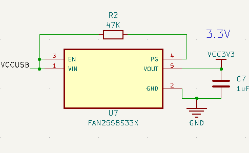
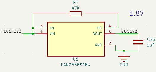
It is built around the T8Q144C3, FAN2558S18X and FAN2558S33X, with the CPDQC3V3C-HF among its other parts. Its parts include 37 capacitors, 32 diodes, 15 resistors, 8 ICs and 6 connectors. It belongs with the fPGA and programmable logic boards of this library.


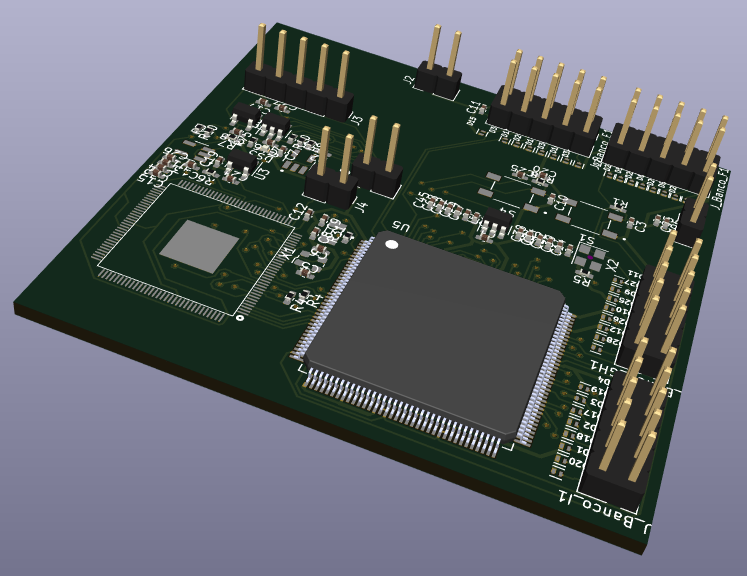
The TEDUN (Tarjeta de Electrónica Digital de la UNAL) is an academic project developed as part of an Embedded Systems course in Electronic Engineering.
⚠️ Note: The project name does not represent an official product of UNAL. It only reflects the academic context in which it was developed.
This project consists of the design and implementation of a custom development board based on:
The board enables hardware experimentation with multiple modules (Bluetooth, audio, infrared, etc.) using communication protocols such as UART, I2S, SPI, and GPIO.
The system integrates:
Used to program the FPGA through OpenOCD running on the F133A.
Stores:
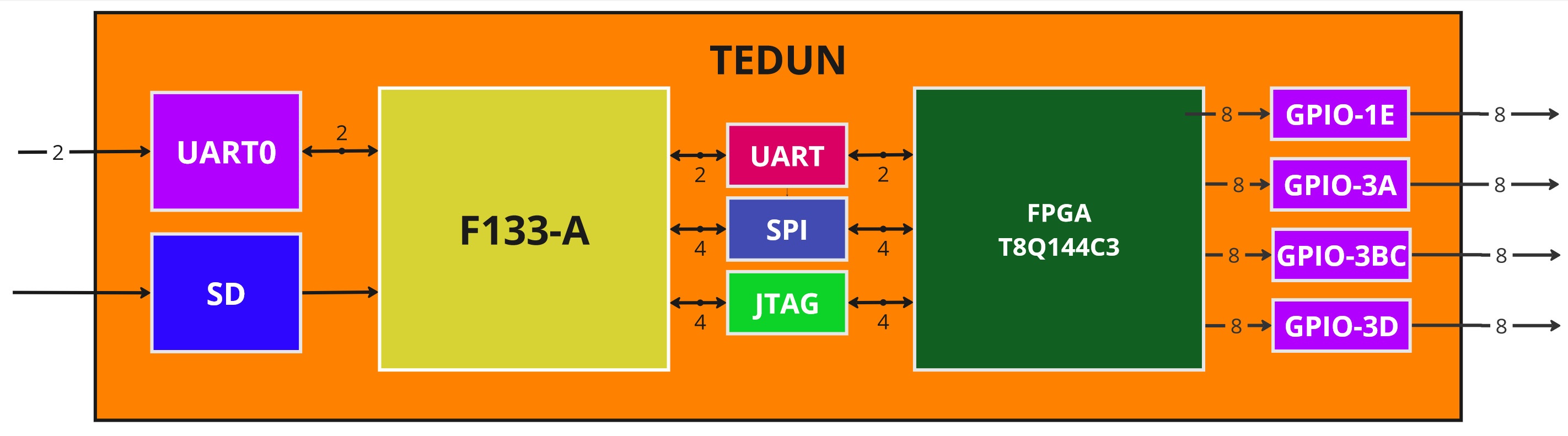
To validate the system, an LctechPi board (F133A-based) was used for testing.
Key points:
Two tools were evaluated:
OpenOCD was compiled for RISC-V and deployed on the board.
Compile OpenOCD from source: https://github.com/riscv/riscv-openocd
Copy binary to: /bin/
Copy scripts to: /usr/local/share/openocd/scripts
Create configuration file: openocd.cfg
adapter driver sysfsgpio
transport select jtag
sysfsgpio jtag_nums 2 3 1 4

set CHIPNAME fpga_trion
source [find fpga/efinix_trion.cfg]

init
pld load fpga_trion.pld GPIO_demo.bitThe hardware design is based on:
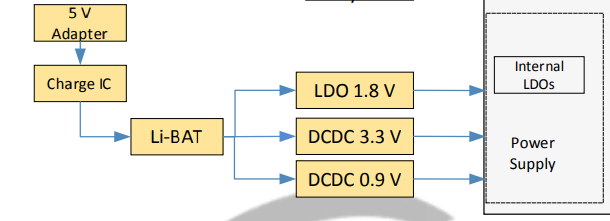
LctechPi board
Trion T8 FPGA reference boards
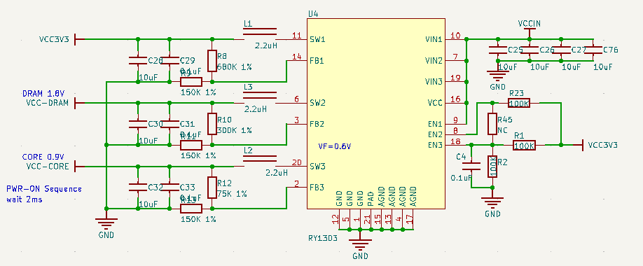
Implemented using:
Sequence:
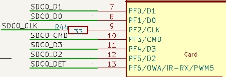
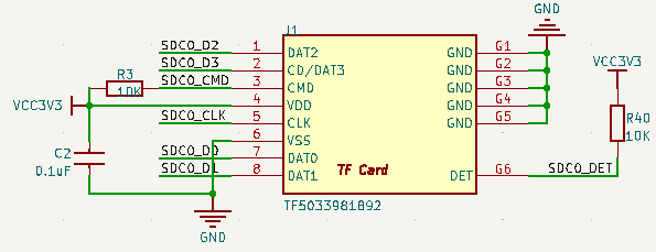
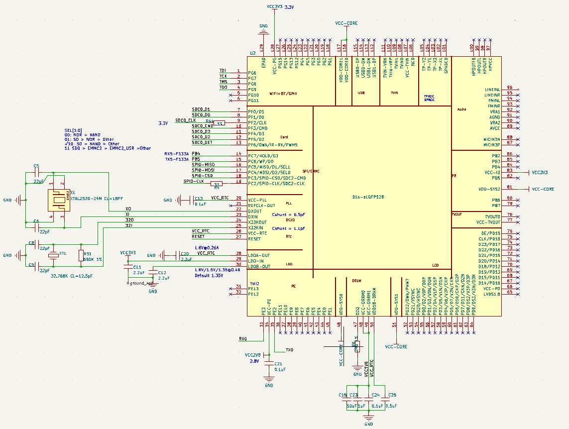
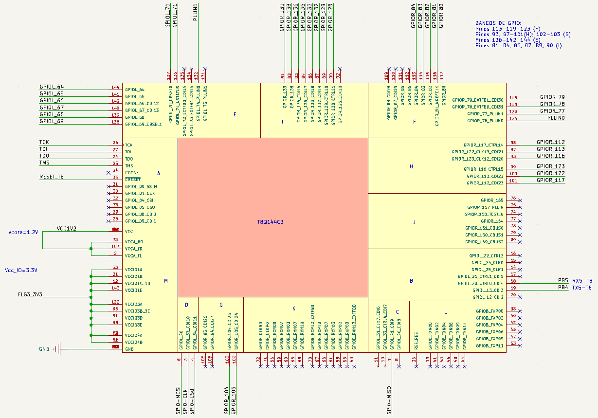
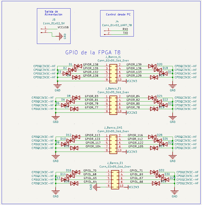
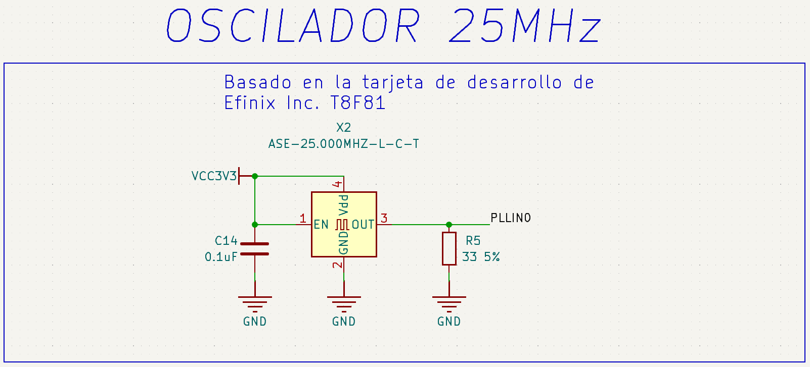
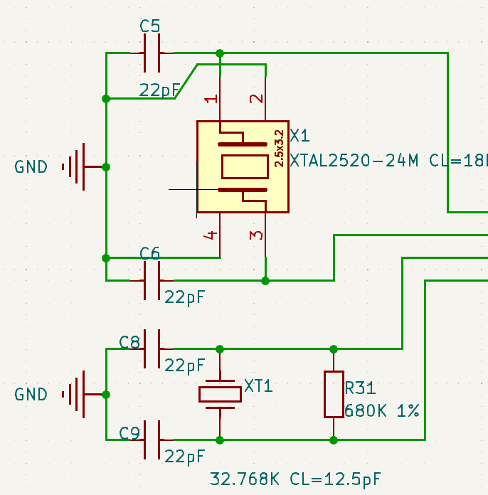
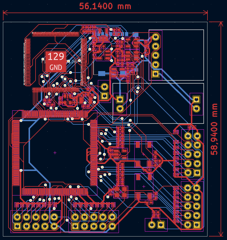
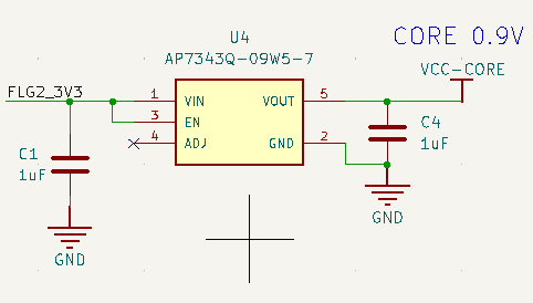
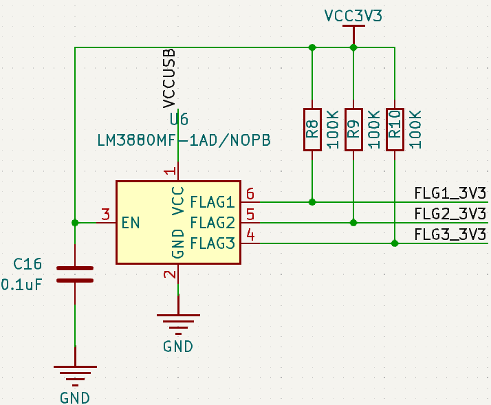
Designed in KiCad:
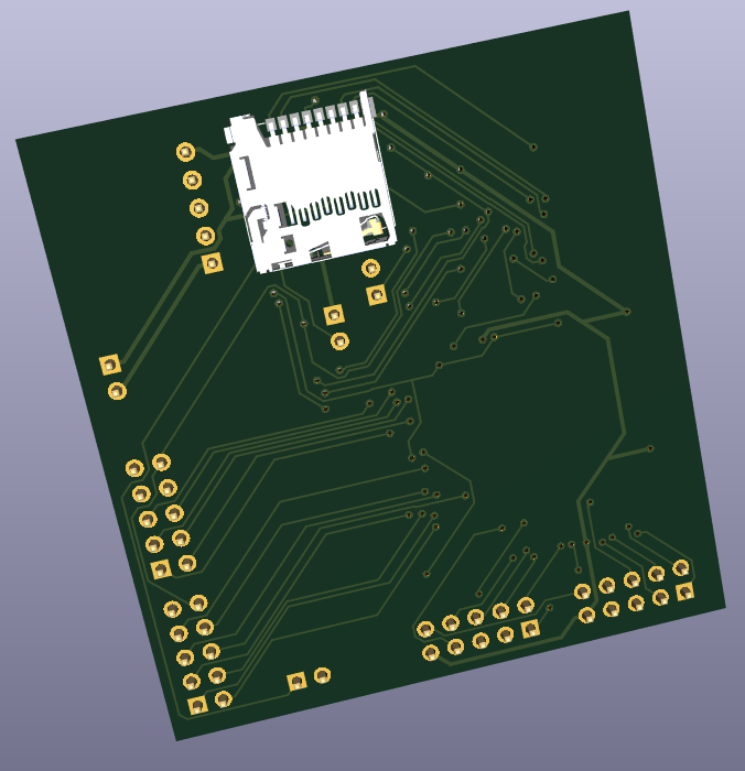
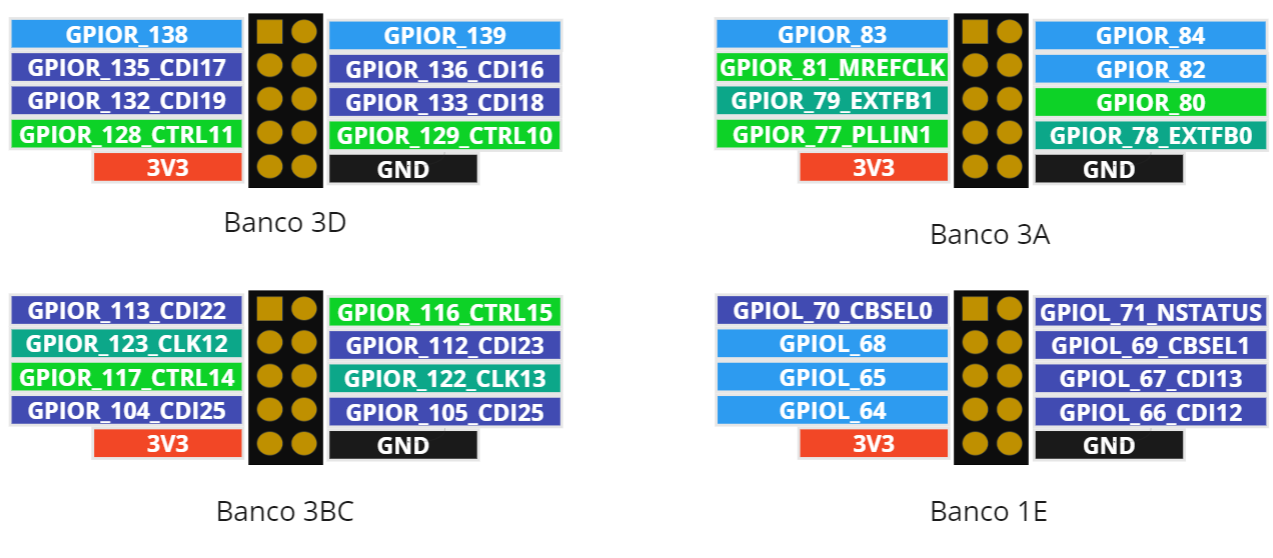

| Qty | Value | Footprint | References |
|---|---|---|---|
| 32 | CPDQC3V3C-HF | DIODFN100X60X42:DIODFN100X60X43-2N | D1, D2, D10, D11, D12, D13, D14, D15, D16, D17, D18, D19, D20, D21, D22, D23 +16 |
| 16 | 0.1uF | Capacitor_SMD:C_0402_1005Metric_Pad0.74x0.62mm_HandSolder | C2, C3, C10, C13, C14, C16, C21, C24, C25, C34, C38, C39, C52, C56, C57, C68 |
| 9 | 1uF | Capacitor_SMD:C_0402_1005Metric_Pad0.74x0.62mm_HandSolder | C1, C4, C7, C17, C19, C23, C26, C27, C28 |
| 5 | 10uF | Capacitor_SMD:C_0402_1005Metric_Pad0.74x0.62mm_HandSolder | C15, C22, C45, C95, C96 |
| 4 | 22pF | Capacitor_SMD:C_0402_1005Metric_Pad0.74x0.62mm_HandSolder | C5, C6, C8, C9 |
| 4 | Conn_02x05_Odd_Even | Connector_PinHeader_2.54mm:PinHeader_2x05_P2.54mm_Vertical | J_Banco_E1, J_Banco_F1, J_Banco_GH1, J_Banco_I1 |
| 3 | 100K | Resistor_SMD:R_0402_1005Metric_Pad0.72x0.64mm_HandSolder | R8, R9, R10 |
| 3 | 10K | Resistor_SMD:R_0402_1005Metric_Pad0.72x0.64mm_HandSolder | R3, R18, R40 |
| 3 | 2.2uF | Capacitor_SMD:C_0402_1005Metric_Pad0.74x0.62mm_HandSolder | C11, C12, C20 |
| 2 | 33 | Resistor_SMD:R_0402_1005Metric_Pad0.72x0.64mm_HandSolder | R4, R44 |
| 2 | 47K | Resistor_SMD:R_0402_1005Metric_Pad0.72x0.64mm_HandSolder | R2, R7 |
| 2 | SW-CE | Button:SW_PTS_647_SM38_SMTR2_LFS | S1, S4 |
| 1 | 10K 1% | Resistor_SMD:R_0402_1005Metric_Pad0.72x0.64mm_HandSolder | R1 |
| 1 | 240 1% | Resistor_SMD:R_0402_1005Metric_Pad0.72x0.64mm_HandSolder | R6 |
| 1 | 32.768K CL=12.5pF | Cristal_TEDUN:Y3215 | XT1 |
| 1 | 33 5% | Resistor_SMD:R_0402_1005Metric_Pad0.72x0.64mm_HandSolder | R5 |
| 1 | 5.1K | Resistor_SMD:R_0402_1005Metric_Pad0.72x0.64mm_HandSolder | R75 |
| 1 | 680K 1% | Resistor_SMD:R_0402_1005Metric_Pad0.72x0.64mm_HandSolder | R31 |
| 1 | AP7343Q-09W5-7 | Package_TO_SOT_SMD:SOT-23-5 | U4 |
| 1 | ASE-25.000MHZ-L-C-T | Oscillator:Oscillator_SMD_Abracon_ASE-4Pin_3.2x2.5mm | X2 |
| 1 | Conn_01x02_5V | Connector_PinHeader_2.54mm:PinHeader_1x02_P2.54mm_Vertical | J5 |
| 1 | Conn_01x02_IN | Connector_PinHeader_2.54mm:PinHeader_1x02_P2.54mm_Vertical | J2 |
| 1 | Conn_01x02_OUT | Connector_PinHeader_2.54mm:PinHeader_1x02_P2.54mm_Vertical | J6 |
| 1 | Conn_01x02_UART_T8 | Connector_PinHeader_2.54mm:PinHeader_1x02_P2.54mm_Vertical | J4 |
| 1 | Conn_01x05_Pin | Connector_PinHeader_2.54mm:PinHeader_1x05_P2.54mm_Vertical | J3 |
| 1 | D1s-eLQFP128 | F133A:F133A_QFP129 | U2 |
| 1 | FAN2558S18X | FAN2558S33X:FAN2558S33X | U1 |
| 1 | FAN2558S33X | FAN2558S33X:FAN2558S33X | U7 |
| 1 | GREEN | LED_SMD:LED_0402_1005Metric_Pad0.77x0.64mm_HandSolder | DS3 |
| 1 | LM3880MF-1AD/NOPB | Package_TO_SOT_SMD:SOT-23-6 | U6 |
| 1 | T8Q144C3 | T8Q144C3:QFP50P2200X2200X160-144N | U5 |
| 1 | TF5033981892 | SD_TEDUN:TFCARD-1040310811 | J1 |
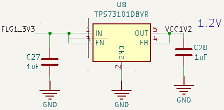
| 1 | TPS73101DBVR | Package_TO_SOT_SMD:SOT-23-5 | U8 |
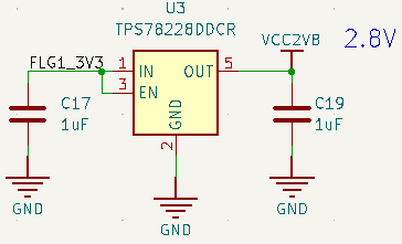
| 1 | TPS78228DDCR | Package_TO_SOT_SMD:SOT-23-5 | U3 |
| 1 | XTAL2520-24M CL=18PF | Oscillator:Oscillator_SMD_ECS_2520MV-xxx-xx-4Pin_2.5x2.0mm | X1 |

logitiles/HEXBERRY-V-20Q100-0.91
Open Hardware FPGA platform


BlueSCSI/BlueSCSI-v2
BlueSCSI v2/Ultra - an open source, open hardware, SCSI emulator using the Pi Pico PR2040 and Pico 2 RP2350


sadekbaroudi/bgkeeb
This is a reversible 100mm x 100mm pcb with support for mx or choc switches (no hotswap), per key led, rotary encoders, and exposes the SDA/SCL/GND/VCC lines in the form of the pimoroni trackball pins (meaning you can…


Nuclear-Squid/Quacken
Libre, ergonomic, polymorphic: a single PCB for many possible layouts.
It measures 56.1 × 58.9 mm and has 2 copper layers, 1.6 mm thick.
108 parts, built around the T8Q144C3, FAN2558S18X, FAN2558S33X and CPDQC3V3C-HF. The full list of its parts is on this page, with links to each part's symbol and footprint where PCBKit's library has them.
From the anyo2002/tedun-digital-electronics-board repository on GitHub, at the commit this page was made from: the board is hardware/kicad/Esquema_TEDUN.kicad_pcb and its schematic hardware/kicad/Esquema_TEDUN.kicad_sch. PCBKit opens the board in the browser, with nothing to install.
Its repository states no licence, so its author keeps all rights: ask anyo2002 before reusing the design.