2 layers
Encoder
byrantech/laptop
anyon_e, a highly integrated, high end, open source laptop. Attempt the impossible.
7 parts4.3kMIT

 ansiwen/dualjoy7
Retro joystick USB adapter
Dualjoy is an open-source printed circuit board by ansiwen, from the ansiwen/dualjoy repository on GitHub, published under the MIT licence. It is a 2-layer board of 66.4 × 56 mm with 7 parts on 40 nets, routed with 34 tracks and 0 vias.
It belongs with the retro computing and games and keyboards and input boards and the RP2040 boards of this library.
This is a firmware for the Rapsberry Pi Pico that turns it into a USB adapter for two D-Sub 9 joysticks, as they where used for example with the Atari 2600 console and the Commodore C64 and Amiga home computers. They will appear as two digital hats/d-pads with only one button.
The code is based on the various examples of the Pico SDK and TinyUSB and keeps their MIT license.
You can use the precompiled binary from the release page if you use the same GPIOs as in the hardware example below:
| GPIO | D-SUB pin | Function |
|---|---|---|
| 10 | 1 (J1) | J1 UP |
| 11 | 2 (J1) | J1 DOWN |
| 12 | 3 (J1) | J1 LEFT |
| 13 | 4 (J1) | J1 RIGHT |
| 9 | 6 (J1) | J1 BTN |
| 18 | 1 (J2) | J2 UP |
| 19 | 2 (J2) | J2 DOWN |
| 20 | 3 (J2) | J2 LEFT |
| 21 | 4 (J2) | J2 RIGHT |
| 17 | 6 (J2) | J2 BTN |
Additionally you need to connect pin 8 of both D-SUB connectors with GND on the Pico.
If you want to use different GPIOs, you easily can build the firmware yourself. Like any other pico project, after installing the Pico SDK you do:
$ mkdir build
$ cd build
$ cmake ..
$ make
If building for the Pico 2 (RP2350), use cmake -DPICO_BOARD=pico2 .. instead.
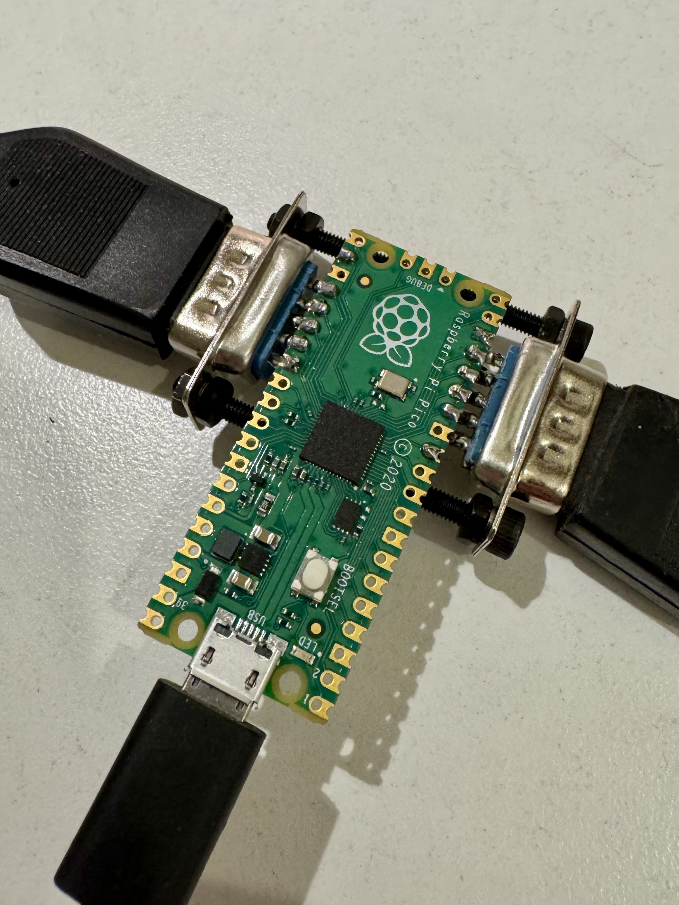
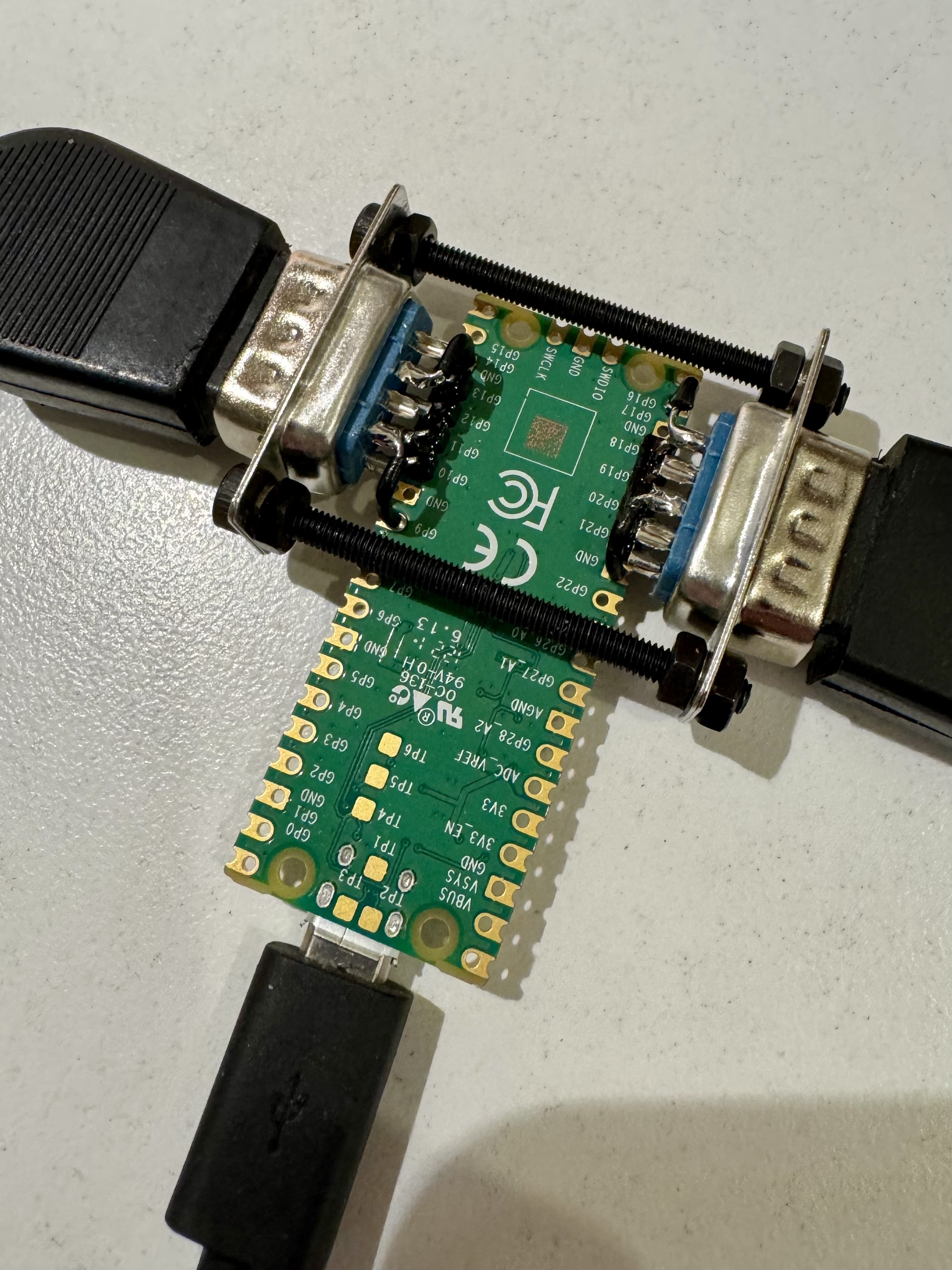
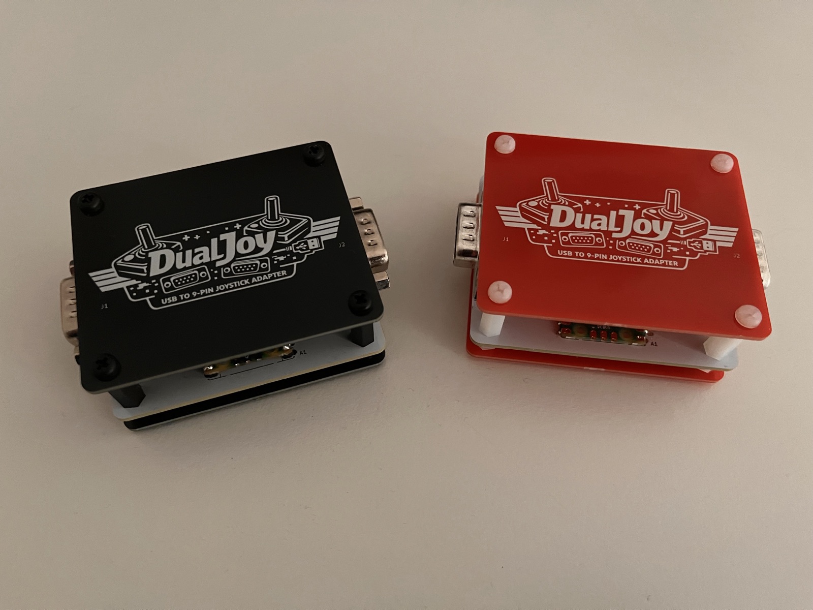
A ready-made PCB with a matching top and bottom plate as enclosure is available in hardware/.
| Qty | Value | Footprint | References |
|---|---|---|---|
| 4 | MountingHole_3.2mm_M3 | MountingHole:MountingHole_3.2mm_M3 | H1, H2, H3, H4 |
| 2 | DE9_Pins | Connector_Dsub:DSUB-9_Pins_Horizontal_P2.77x2.84mm_EdgePinOffset9.90mm_Housed_MountingHolesOffset11.32mm | J1, J2 |
| 1 | RaspberryPi_Pico | Module:RaspberryPi_Pico_Common_Unspecified | A1 |
It measures 66.4 × 56 mm and has 2 copper layers, 1.6 mm thick.
7 parts. The full list of its parts is on this page, with links to each part's symbol and footprint where PCBKit's library has them.
From the ansiwen/dualjoy repository on GitHub, at the commit this page was made from: the board is hardware/kicad/dualjoy.kicad_pcb and its schematic hardware/kicad/dualjoy.kicad_sch. PCBKit opens the board in the browser, with nothing to install.
Its repository publishes it under the MIT licence: you may reuse it on that licence's terms (keep the author's notice, and for a copyleft licence share your changes alike).
byrantech/laptop
anyon_e, a highly integrated, high end, open source laptop. Attempt the impossible.


AxxAxx/AxxSolder
STM32 Based soldering station for JBC cartridges, 9-24 VDC and USB-PD power


jamro/tiny-engineer
A small desktop robot that brings an AI coding assistant to life, physically acting out when it reads files, thinks, writes code, and finishes work.

hoglet67/RGBtoHDMI
Bare-metal Raspberry Pi project that provides pixel-perfect sampling of Retro Computer RGB/YUV video and conversion to HDMI
