2 layers0.5 × 31.1 mm
 aneeshlingala/FirstResponderSystem
reverie hacks submission
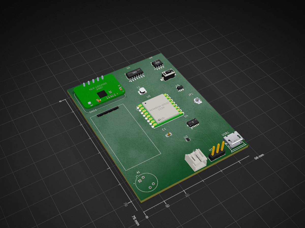
Survivornode is an open-source printed circuit board by aneeshlingala, from the aneeshlingala/FirstResponderSystem repository on GitHub. It is a 2-layer board of 56 × 75 mm with 16 parts on 40 nets, routed with 264 tracks and 16 vias.
It is built around the MLX90640ESF-BAA-000-TU, ADXL345BCCZ-RL7 and AP2112K-3.3TRG1, with the HLK-LD2410C, RFM95W-915S2 and S2B-PH-K-S(LF)(SN) among its other parts. Its parts include 9 ICs, 1 capacitor and 1 inductor. It belongs with the AVR (ATmega, ATtiny) boards of this library.


During major disasters, first responders (police, fire, medical) do not have a reliable way to track their environment, find survivors, and receive information in real time. Existing systems can be expensive, hard to deploy, or require additional personnel to operate, wasting manpower that can be used from more urgent tasks.
The FirstResponderSystem uses cheap to manufacture, durable, and easy-to-deploy custom-made PCBs that create a centralized long-range radio network suited for emergencies instead of relying on broken or buggy connection systems (WiFi, Mobile Data, etc). By providing real-time sensor data and survivor detection, FirstResponderSystem allows emergency personnel to analyze dangerous conditions, locate any survivors, and make safe decisions while allowing responders to work on more urgent things. The data can also be sent to other organizations to relay information to people in the area, declare evacuations/emergencies, and more. The survivor node can be put in rubble to detect survivors, while the environmental node can be put in various parts of the disaster area. Multiple survivor and environmental nodes can be used at once.
Survivor PCB
Environmental PCB
Broadcast PCB
Computer Software
The PCBS were made in KiCAD 10 with footprints and symbols from LCSC, bundled KiCAD files, and SnapEDA.
All of the PCBS come with images:
All of the PCBS come with code made in PlatformIO in VSCode. The programming language used to make the code is C++. The code successfully compiles with the firmware file in the .pio/build/[MCU NAME]/ and uses a good amount of 3rd-party libraries to interface with various components.
The folders inside the survivornode, broadcastnode, or environmental node are structured as follows:
The computer_code folder has a reciever.exe file for running on Windows without any dependencies being required to be installed. The reciever.py file can be run universally and requires Tkinter (already installed on most Python distributions), pyserial, and Python 3.13+ to run.
I learned how to make PCBs in KiCad 10 with proper symbols and footprints. I also learned how to use the design and electrical rules checker to make sure my project met all of the rules.
Some challenges I faced included having issues with footprint/symbol quality, finding proper footprints for some of my component choices, and exporting gerbers. I solved these issues by searching up solutions online and using external plugins to export gerbers properly since it was bugged out with LCSC symbols.
| Qty | Value | Footprint | References |
|---|---|---|---|
| 1 | ADXL345BCCZ-RL7 | easyeda2kicad:LGA-14_L5.0-W3.0-P0.80-BL | U4 |
| 1 | AP2112K-3.3TRG1 | easyeda2kicad:SOT-25-5_L2.9-W1.6-P0.95-LS2.8-BL | U9 |
| 1 | ATTINY1614-SSNR | easyeda2kicad:SOIC-14_L8.7-W3.9-P1.27-LS6.0-BL | U1 |
| 1 | CL10A105KB8NNNC | easyeda2kicad:C0603 | C1 |
| 1 | FNR3015S2R2MT | easyeda2kicad:IND-SMD_L3.0-W3.0_FNR30XXS | L1 |
| 1 | HLK-LD2410C | HLK-LD2410C:MODULE_HLK-LD2410C | U3 |
| 1 | Header-Male-2.54_1x3 | easyeda2kicad:HDR-TH_3P-P2.54-V-M-1 | H1 |
| 1 | MICRO5.9MMUSB | easyeda2kicad:MICRO-USB-SMD_5P-P0.65-H-F_MICRO5.9MMUSB | USB1 |
| 1 | MLX90640ESF-BAA-000-TU | MLX90640ESF-BAA-000-TU:TO292P930H600-4 | A1 |
| 1 | RCWL-0516 | RCWL-0516:RCWL-0516 | SNS1 |
| 1 | RFM95W-915S2 | easyeda2kicad:WIRELM-SMD_16P-L16.0-W16.0-P2.00_LORA-CC68-915MHZ-TCXO | U5 |
| 1 | S2B-PH-K-S | easyeda2kicad:CONN-TH_S2B-PH-K-S-LF-SN | U7 |
| 1 | TP4056 | easyeda2kicad:ESOP-8_L4.9-W3.9-P1.27-LS6.0-BL-EP | U8 |
| 1 | TPS61023DRLR | easyeda2kicad:SOT-563_L1.6-W1.2-P0.50-LS1.6-BR | U2 |
| 1 | U.FL-R-SMT-1 | easyeda2kicad:ANT-SMD_UFL-R-SMT-1-10 | JP1 |
| 1 | YZA-032-5.0W | easyeda2kicad:SW-SMD_L6.0-W3.5-LS8.0 | U6 |


ephemerkey/ephemerkey
The consumer half of the ephemerkey system, and the second PCB in this repo (alongside hardware/ephemerkey/, sharing the same scripts/kschgen.py engine, Makefile, and lib tables — the multi-project layout used by…

Circuit-Digest/Smart-Universal-Remote-with-Learning-function-and-Google-Assistant-Support
Smart Universal Remote with Learning function and Google Assistant Support

crowdaware-inno-wing-iot/crowdaware-node
Scalable, privacy-aware crowd flow monitoring

Heartland-Data/esp32-mintia-sensor-kit
本リポジトリは、MINTIAケースにESP32と各種センサを組み込む試作用ファームウェアの参考実装です。


jhbryan0817-del/IoT_Beyond_Lab_Thermal_ML
Privacy-oriented thermal occupancy estimation with edge ML for HKU learning spaces.

Momozavur/F7FC-V0.1
Open the appropriate .kicadpro file in KiCad; .pro entries are legacy projects. Keep schematics, boards, local libraries, library tables, and supporting files together.
It measures 56 × 75 mm and has 2 copper layers, 1.6 mm thick.
16 parts, built around the MLX90640ESF-BAA-000-TU, ADXL345BCCZ-RL7, AP2112K-3.3TRG1 and HLK-LD2410C. The full list of its parts is on this page, with links to each part's symbol and footprint where PCBKit's library has them.
From the aneeshlingala/FirstResponderSystem repository on GitHub, at the commit this page was made from: the board is survivornode/pcb_data/survivornode.kicad_pcb and its schematic broadcastnode/pcb_data/broadcastnode.kicad_sch. PCBKit opens the board in the browser, with nothing to install.
Its repository states no licence, so its author keeps all rights: ask aneeshlingala before reusing the design.