2 layers
 androiders/pcbs
Rpo for pcb layouts, gerber and gcode files
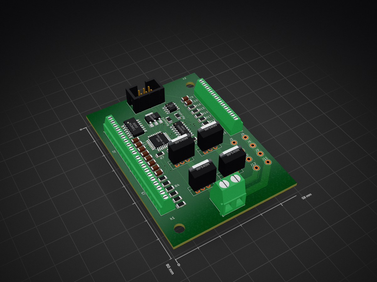
Mc unit is an open-source printed circuit board by androiders, from the androiders/pcbs repository on GitHub. It is a 2-layer board of 58 × 80 mm with 54 parts on 62 nets, routed with 682 tracks and 34 vias.
It is built around the ATMEGA8L-8AU, 74HC14 and AMS1117, with the ULN2003 and IRF540N among its other parts. Its parts include 20 resistors, 13 connectors, 10 capacitors, 5 ICs and 4 transistors. It belongs with the AVR (ATmega, ATtiny) boards of this library.


View this project on CADLAB.io.
Repo for pcb layouts, gerber and gcode files
Current isolation mill depth to test: 0.04 mm (0.05 was tested and seems to work fine!) (Common copper depth is about 0.03 mm)
Current feedrate on isolation milling to test: 60 mm/s
spindle speed 12000 rpm
use 0.2 mm tool width on cnc generation
2 passes with 0.1 overlap
| Qty | Value | Footprint | References |
|---|---|---|---|
| 20 | R | Resistor_SMD:R_1206_3216Metric | R1, R2, R3, R4, R5, R6, R7, R10, R11, R12, R13, R14, R15, R16, R17, R18 +4 |
| 10 | C | Capacitor_SMD:C_1206_3216Metric | C1, C2, C3, C4, C5, C6, C7, C8, C9, C10 |
| 8 | Conn_01x01_Female | Connector_Pin:Pin_D1.0mm_L10.0mm_LooseFit | J4, J5, J6, J7, J9, J10, J11, J12 |
| 4 | IRF540N | Package_TO_SOT_THT:TO-220-3_Vertical | Q1, Q2, Q3, Q4 |
| 2 | MountingHole_4.3mm_M4 | MountingHole:MountingHole_4.3mm_M4 | h1, h2 |
| 1 | 12 v in | TerminalBlock_Phoenix:TerminalBlock_Phoenix_MKDS-1,5-2-5.08_1x02_P5.08mm_Horizontal | J1 |
| 1 | 74HC14 | Package_SO:SO-14_5.3x10.2mm_P1.27mm | U1 |
| 1 | AMS1117 | Package_TO_SOT_SMD:SOT-223-3_TabPin2 | U2 |
| 1 | ATmega8L-8A | Package_QFP:TQFP-32_7x7mm_P0.8mm | U3 |
| 1 | AVR-ISP-6 | Connector_IDC:IDC-Header_2x03_P2.54mm_Vertical | J8 |
| 1 | Opamp_Dual | Package_SO:SOIC-8_3.9x4.9mm_P1.27mm | U5 |
| 1 | Screw_Terminal_01x10 | TerminalBlock_Phoenix:TerminalBlock_Phoenix_MPT-0,5-10-2.54_1x10_P2.54mm_Horizontal | J3 |
| 1 | Screw_Terminal_01x12 | TerminalBlock_Phoenix:TerminalBlock_Phoenix_MPT-0,5-12-2.54_1x12_P2.54mm_Horizontal | J13 |
| 1 | ULN2003 | Package_SO:SOIC-16_3.9x9.9mm_P1.27mm | U4 |
| 1 | in1 | TerminalBlock_Phoenix:TerminalBlock_Phoenix_MPT-0,5-10-2.54_1x10_P2.54mm_Horizontal | J2 |
It measures 58 × 80 mm and has 2 copper layers, 1.6 mm thick.
54 parts, built around the ATMEGA8L-8AU, 74HC14, AMS1117 and ULN2003. The full list of its parts is on this page, with links to each part's symbol and footprint where PCBKit's library has them.
From the androiders/pcbs repository on GitHub, at the commit this page was made from: the board is mc unit/mc unit.kicad_pcb. PCBKit opens the board in the browser, with nothing to install.
Its repository states no licence, so its author keeps all rights: ask androiders before reusing the design.


dilshan/programmable-light
Simple time based programmable light controller

rwth-afu/RasPagerC9000
Adapted Version of RasPager to generate Signals for Ericsson C9000 Paging Transmitter


niyathiarun/Analog-Mixed-Signal-PCB
Analog–Mixed Signal PCB project featuring ATmega8L microcontroller and op-amp interface, designed and fabricated using KiCad.


LinJesUxUs/TermoHumi
Thermo-hygrometer code, powered on ATMega, AHT10 sensor and 7 Segment Display.


KerimAltuntecim/esp32-pcb-control-system
ESP32-C3 PCB control system with Nextion HMI, motor, sensor and power-driver interfaces.