
4 layers55 × 56.4 mm

 andrewhlu/spl1
Smart Parking Lot Capstone Project
Spl prototype is an open-source printed circuit board by andrewhlu, from the andrewhlu/spl repository on GitHub. It is a 2-layer board of 71.6 × 68.6 mm with 78 parts on 101 nets, routed with 771 tracks and 66 vias.
It is built around the LP2985-33DBV and RM3100-U. Its parts include 32 capacitors, 22 resistors, 8 ICs, 6 connectors and 5 diodes. It belongs with the STM32 boards of this library.



A project for ECE 189 - Computer Engineering Capstone led by Professor Isukapalli at UC Santa Barbara
Drivers spend too much time in parking lots trying to find an open space to park in. Many parking lots only have per-floor capacity indicators, and existing solutions are prohibitively expensive.
What if we could utilize low-cost sensors and a companion application to navigate drivers to empty parking spots faster, at a low cost to facility owners?
The goal of this project is to design a smart parking lot that will direct drivers to the nearest open parking space in an efficient, accurate, and clean manner.
We accomplish this using:
For a more detailed description, please take a look at our project presentation slides.
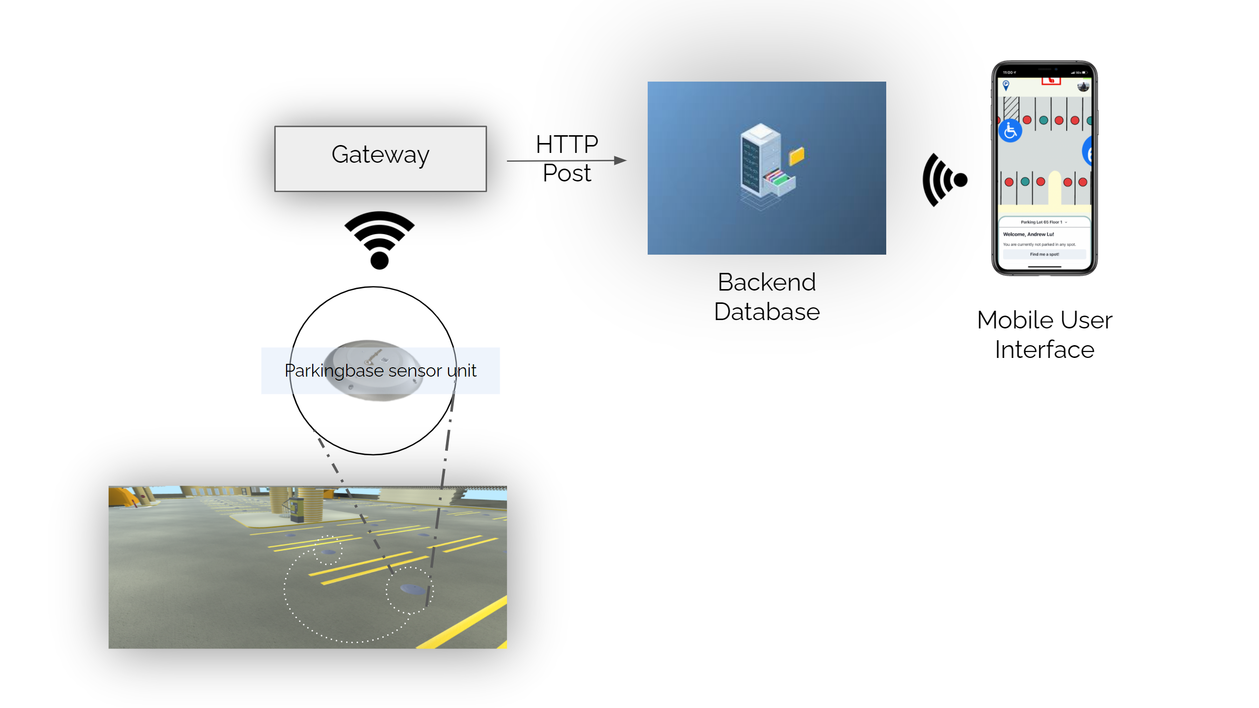
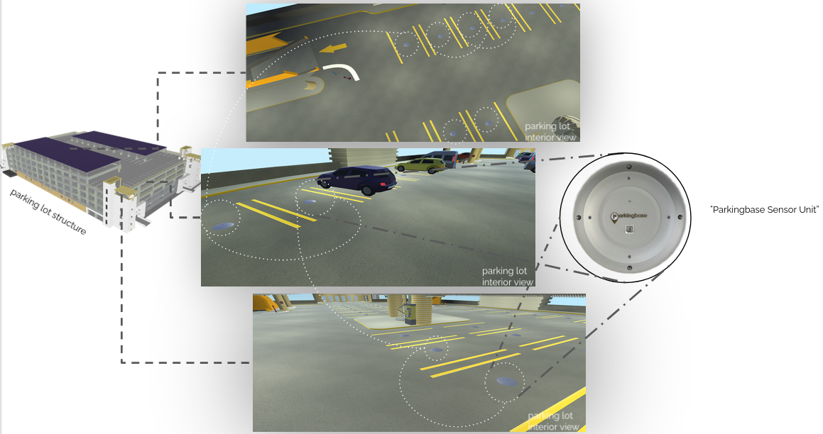
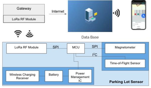
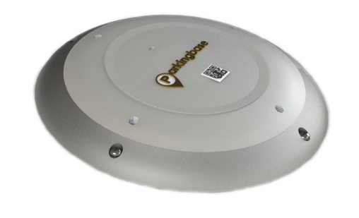
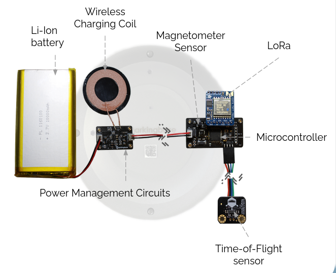
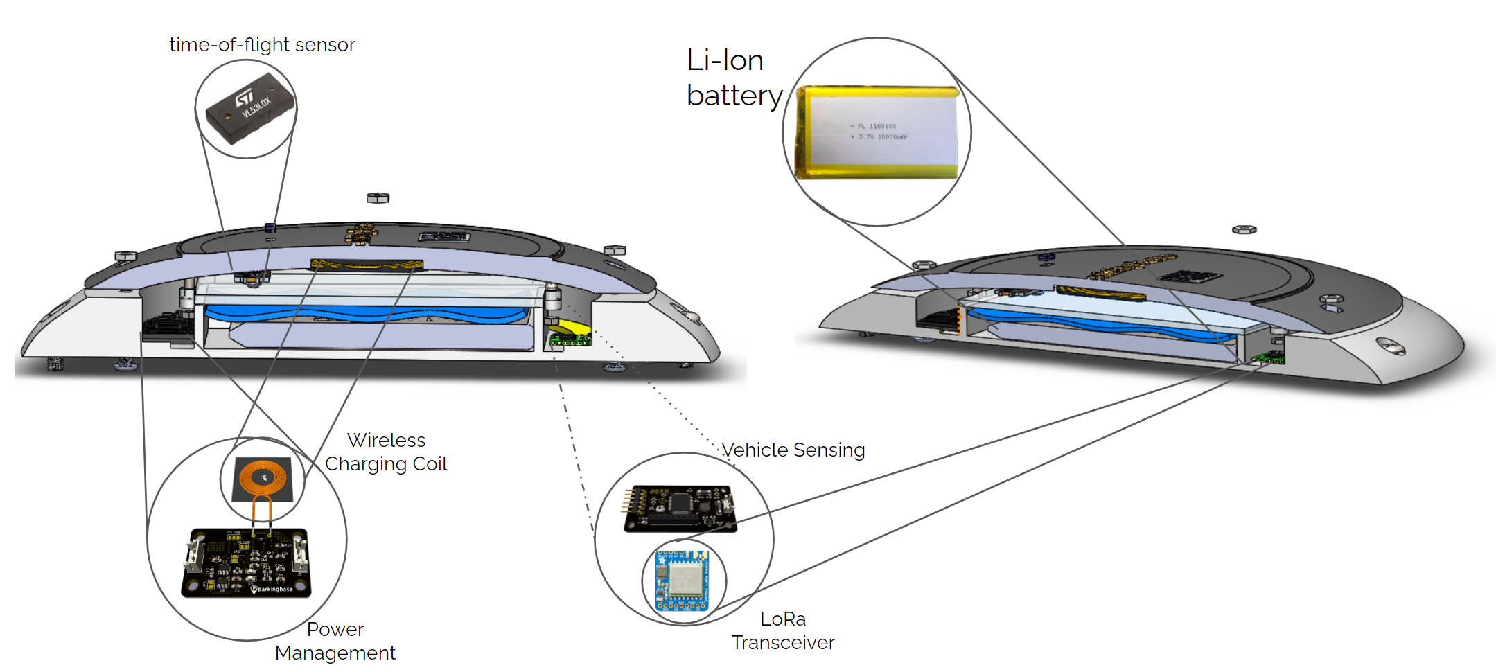
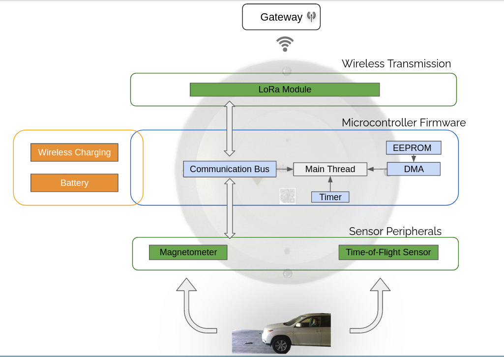
The raw Kicad design files can be found in the pcb-design folder in our repo.
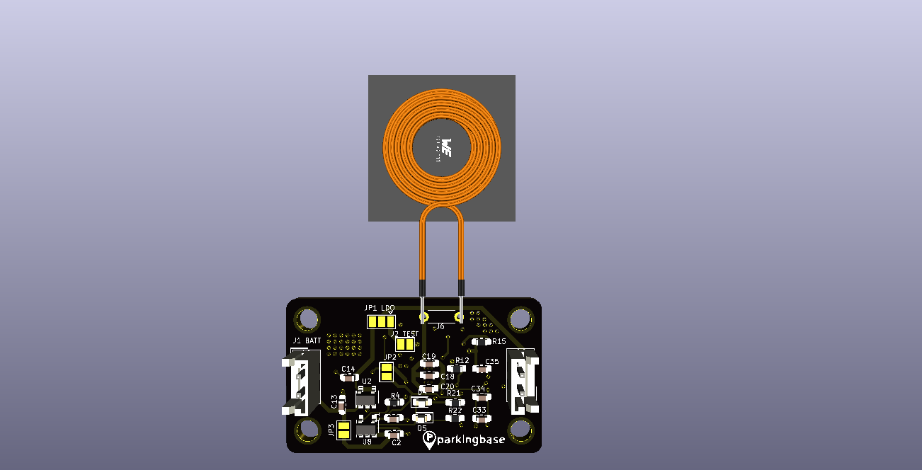
Driver User Interface:

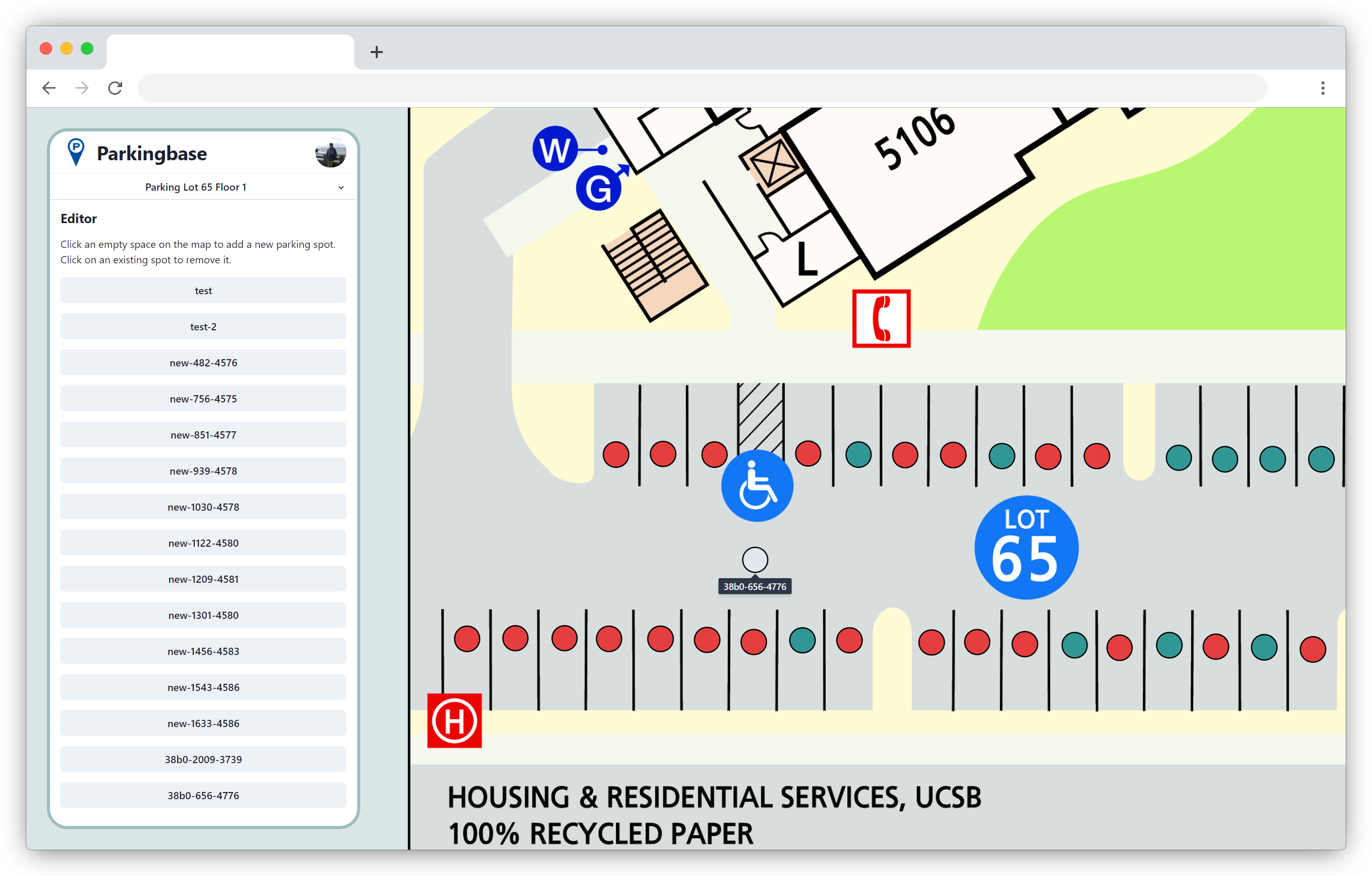
Editor User Interface:
Fall Quarter Review Presentation
.markdown-body h1:first-of-type { display: none; } .center { text-align: center; padding: 1rem; }| Qty | Value | Footprint | References |
|---|---|---|---|
| 6 | 104 | Capacitor_SMD:C_0805_2012Metric_Pad1.18x1.45mm_HandSolder | C5, C6, C7, C8, C9, C14 |
| 6 | 121 | Resistor_SMD:R_0805_2012Metric_Pad1.20x1.40mm_HandSolder | R6, R7, R8, R9, R10, R11 |
| 5 | LED | LED_SMD:LED_0805_2012Metric_Pad1.15x1.40mm_HandSolder | D1, D2, D3, D4, D5 |
| 4 | 10uF | Capacitor_SMD:C_0805_2012Metric_Pad1.18x1.45mm_HandSolder | C1, C2, C3, C4 |
| 3 | 10nF 50V | Capacitor_SMD:C_0805_2012Metric_Pad1.18x1.45mm_HandSolder | C25, C26, C32 |
| 3 | 1uF 50V | Capacitor_SMD:C_0805_2012Metric_Pad1.18x1.45mm_HandSolder | C13, C33, C35 |
| 3 | R_Small | Resistor_SMD:R_0805_2012Metric_Pad1.20x1.40mm_HandSolder | R1, R2, R20 |
| 2 | 100nF 50V | Capacitor_SMD:C_0805_2012Metric_Pad1.18x1.45mm_HandSolder | C31, C34 |
| 2 | 10k | Resistor_SMD:R_0805_2012Metric_Pad1.20x1.40mm_HandSolder | R16, R18 |
| 2 | 1K | Resistor_SMD:R_0805_2012Metric_Pad1.20x1.40mm_HandSolder | R21, R22 |
| 2 | 20pF | Capacitor_SMD:C_0805_2012Metric_Pad1.18x1.45mm_HandSolder | C10, C11 |
| 2 | 22nF 50V | Capacitor_SMD:C_0805_2012Metric_Pad1.18x1.45mm_HandSolder | C23, C28 |
| 2 | 470nF 50V | Capacitor_SMD:C_0805_2012Metric_Pad1.18x1.45mm_HandSolder | C24, C27 |
| 2 | 68nF 50V | Capacitor_SMD:C_0805_2012Metric_Pad1.18x1.45mm_HandSolder | C18, C19 |
| 2 | C_Small | Capacitor_SMD:C_0805_2012Metric_Pad1.18x1.45mm_HandSolder | C12, C29 |
| 2 | Conn_01x02_Female | Connector_JST:JST_EH_B2B-EH-A_1x02_P2.50mm_Vertical | J1, J2 (TEST3V3-GND) |
| 2 | Jumper | Connector_PinHeader_2.54mm:PinHeader_1x02_P2.54mm_Vertical | JP2(BQ-5V), JP3(CHG-BATT) |
| 2 | NC | Resistor_SMD:R_0805_2012Metric_Pad1.20x1.40mm_HandSolder | R12, R15 |
| 1 | 100pF 50V | Capacitor_SMD:C_0805_2012Metric_Pad1.18x1.45mm_HandSolder | C22 |
| 1 | 10K | Resistor_SMD:R_0805_2012Metric_Pad1.20x1.40mm_HandSolder | R3 |
| 1 | 10uF 50V | Capacitor_SMD:C_0805_2012Metric_Pad1.18x1.45mm_HandSolder | C30 |
| 1 | 1800pF 50V | Capacitor_SMD:C_0805_2012Metric_Pad1.18x1.45mm_HandSolder | C21 |
| 1 | 180R | Resistor_SMD:R_0805_2012Metric_Pad1.20x1.40mm_HandSolder | R14 |
| 1 | 2K | Resistor_SMD:R_0805_2012Metric_Pad1.20x1.40mm_HandSolder | R4 |
| 1 | 33k | Resistor_SMD:R_0805_2012Metric_Pad1.20x1.40mm_HandSolder | R5 |
| 1 | 3K3 | Resistor_SMD:R_0805_2012Metric_Pad1.20x1.40mm_HandSolder | R19 |
| 1 | 47nF 50V | Capacitor_SMD:C_0805_2012Metric_Pad1.18x1.45mm_HandSolder | C20 |
| 1 | 62R | Resistor_SMD:R_0805_2012Metric_Pad1.20x1.40mm_HandSolder | R13 |
| 1 | 8MHz | Crystal:Crystal_SMD_HC49-SD | Y1 |
| 1 | Coil | Connector_PinHeader_2.54mm:PinHeader_1x02_P2.54mm_Vertical | J6 (COIL) |
| 1 | Conn_01x04_Male | Connector_PinHeader_2.54mm:PinHeader_1x04_P2.54mm_Vertical | J7 (TOF) |
| 1 | DebugPortal | Connector_PinHeader_2.54mm:PinHeader_1x06_P2.54mm_Vertical | J4 |
| 1 | Jumper_3_Open | Connector_PinHeader_2.54mm:PinHeader_1x03_P2.54mm_Vertical | JP1(LDO/TEST3V3) |
| 1 | LP2985-3.3 | Package_TO_SOT_SMD:SOT-23-5 | U2 |
| 1 | LoRaConn | Connector_PinSocket_2.54mm:PinSocket_1x09_P2.54mm_Vertical | J3 |
| 1 | MCP73831-2-OT | Package_TO_SOT_SMD:SOT-23-5 | U8 |
| 1 | NC/10k | Resistor_SMD:R_0805_2012Metric_Pad1.20x1.40mm_HandSolder | R17 |
| 1 | RM3100 | RM3100:QFN-28_EP_4x4_Pitch0.4mm | U3 |
| 1 | STM32L053R8Tx | Package_QFP:LQFP-64_10x10mm_P0.5mm | U1 |
| 1 | SW_Push | Button_Switch_SMD:SW_SPST_B3U-1000P | SW1 |
| 1 | Sen-X | RM3100:RM3100_SEN_XY | U4 |
| 1 | Sen-Y | RM3100:RM3100_SEN_XY | U5 |
| 1 | Sen-Z | RM3100:RM3100_SEN_Z | U6 |
| 1 | bq51013b | bq51013b:VQFN20 | U7 |
It measures 71.6 × 68.6 mm and has 2 copper layers, 1.6 mm thick.
78 parts, built around the LP2985-33DBV and RM3100-U. The full list of its parts is on this page, with links to each part's symbol and footprint where PCBKit's library has them.
From the andrewhlu/spl repository on GitHub, at the commit this page was made from: the board is pcb_design/version_01/spl_prototype.kicad_pcb. PCBKit opens the board in the browser, with nothing to install.
Its repository states no licence, so its author keeps all rights: ask andrewhlu before reusing the design.


jayis1/hacker-devices
Full-cycle hardware designs for security research devices — each device is a subfolder with its own README, schematics, PCB layout, and software stack


anjennings/Tom80
2B is the "definitive" version so all code going forward is designed for that version of the board. Minor hardware differences mean that code for 2.0 may not work on 2.0B without tweaks (mostly related to ram banking)

anthony-bernaert/ftdi-jtag-programmer
FTDI-based JTAG Programmer Circuit for FPGAs

emeb/up5k_osc
The brute-force approach is to synthesize these analog waveforms at sufficiently high sample rates that the timing jitter becomes imperceptible.