4 layers22 × 18.5 mm
 AndersBNielsen/PhaseLatch46
20MHz bandwidth SDR IQ ADC
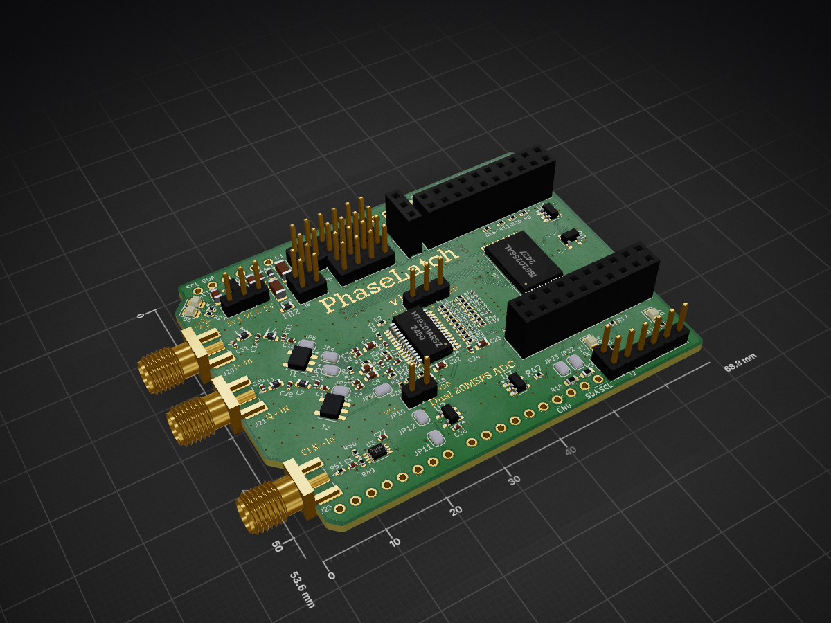
PhaseLatch is an open-source printed circuit board by AndersBNielsen, from the AndersBNielsen/PhaseLatch repository on GitHub. It is a 4-layer board of 68.8 × 53.6 mm with 140 parts on 153 nets, routed with 1,024 tracks and 257 vias.
It is built around the HT9201ARSZ, SN74LVC1G132DCKR-TP and 74LVC2G74DP, with the MIC5504-3.3YM5 among its other parts. Its parts include 51 resistors, 33 capacitors, 10 connectors, 8 ICs and 7 diodes. It belongs with the radio and wireless boards of this library.


PhaseLatch – 6502-Interfaced High-Speed ADC for Experimental SDR
Blog post & video: https://abnielsen.com/2025/12/24/6502-and-a-20mhz-adc-takes-up-the-challenge/
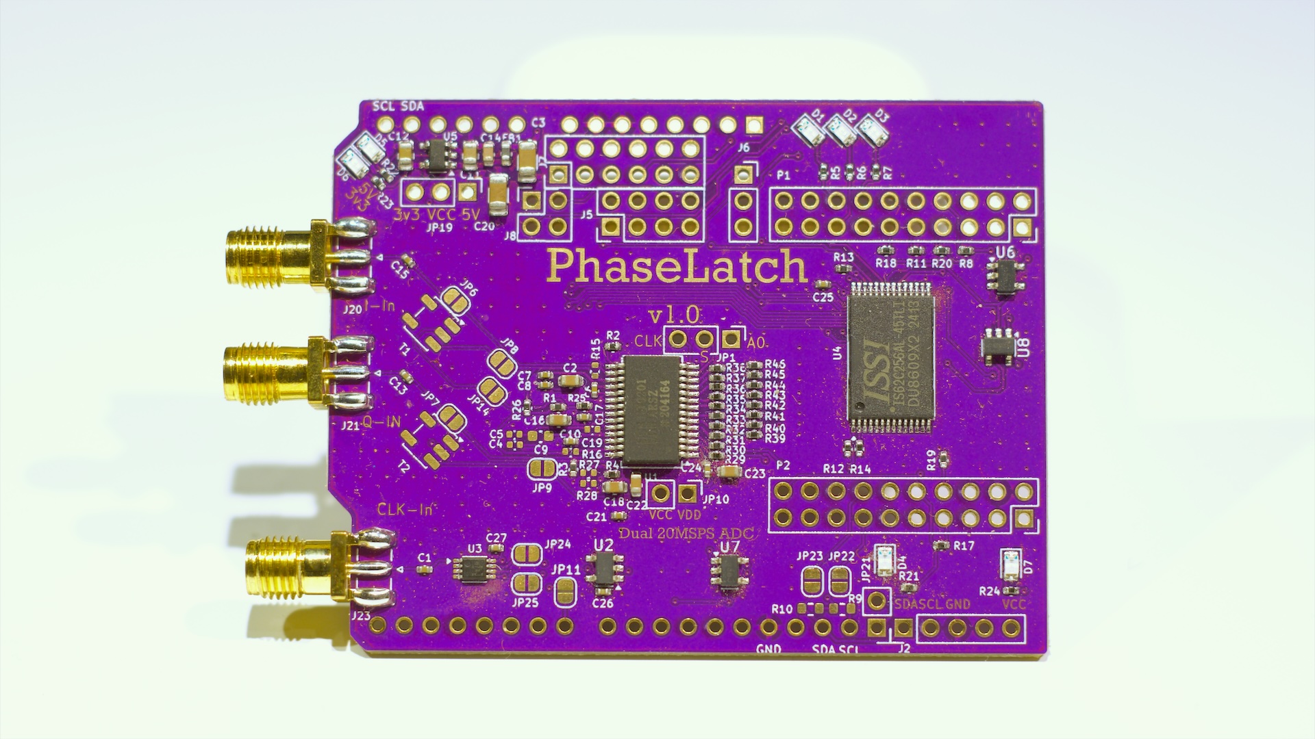
PhaseLatch is an open-source hardware project that explores how far a classic MOS 6502-class CPU can be pushed into modern signal-processing territory. The board implements a dual-channel, 10-bit, 20 MSPS analog-to-digital converter with a straight binary parallel output, allowing the ADC to be memory-mapped directly onto a 6502 (8 bit) data bus.
Unlike typical SDR designs that rely on high-performance microcontrollers or FPGAs, PhaseLatch intentionally interfaces high-speed conversion hardware with a severely resource-constrained 8-bit CPU. This makes it a platform for experimenting with timing limits, bus contention, memory expansion, and minimalist DSP techniques such as Goertzel tone detection executed entirely on the 6502.
The board is designed as a modular Arduino-shield-style form factor and is intended to stack with the PhaseLoom IQ mixer and the 65uino 6502 system. Direct access to the CPU address, data, and control signals enables single-instruction ADC reads and deterministic sampling under software control.
PhaseLatch is not intended to achieve full theoretical ADC bandwidth on a 6502. Instead, it serves as a practical exploration of real-world limitations, architectural trade-offs, and creative signal-processing approaches on vintage computing hardware.
Interested in owning a PhaseLatch?
Buy one here.
6502 source code still lives over on the 65uino project
The main 65uino firmware currently comes with support for the PhaseLatch built in. Time of writing, use the SDR branch.
To get the full bandwidth out of PhaseLatch, it can also be used with an FX2LP USB streaming board instead of the 65uino.
The software/ folder contains the USB streamer firmware + host-side tools for getting PhaseLatch data into SDR software.
/tmp/iq.fifo for Gqrx).PhaseLatch includes header footprints intended for wiring to an FX2LP dev board. The FX2LP provides USB 2.0 high‑speed bulk streaming and acts as the “bridge” from the ADC to a host PC.
At a high level the flow is:
/tmp/iq.fifo so Gqrx can open itStart with the guide in software/README.md, then use software/examples/pipeline.sh for a one-command stream to /tmp/iq.fifo.
jlcpcb/gerber/ folder contains all necessary files for PCB fabrication.production_files/ folder includes:
BOM-PhaseLatch.csv: Bill of MaterialsCPL-PhaseLatch.csv: Component Placement ListGERBER-PhaseLatch.zip: Zipped Gerber files for easy uploadThis project is kindly sponsored by JLCPCB. They offer cheap, professional looking PCBs and super fast delivery.
Step 1: Get the gerber file zip package from the /hardware folder
Step 2: Upload to JLCPCB https://jlcpcb.com/?from=Anders_N

Step 3: Pick your color, surface finish and order.


You can use these affiliate links to get a board for $2 and also get $54 worth of New User Coupons at: https://jlcpcb.com/?from=Anders_N
And in case you also want to order a 3D-printed case you can use this link. How to Get a $7 3D Printing Coupon: https://3d.jlcpcb.com/?from=Anders3DP
For more details, technical explanations, and the full story behind PhaseLoom, check out the project video and documentation. Special thanks to JLCPCB and Fnirsi for supporting the development of this project!
| Qty | Value | Footprint | References |
|---|---|---|---|
| 18 | 10k | Resistor_SMD:R_0402_1005Metric | R4, R5, R6, R11, R12, R13, R14, R17, R18, R19, R20, R21, R22, R23, R24, R48 +2 |
| 16 | 100nF | Capacitor_SMD:C_0402_1005Metric | C1, C4, C5, C6, C7, C8, C10, C13, C15, C17, C19, C21, C24, C25, C26, C27 |
| 12 | 33 | Resistor_SMD:R_0402_1005Metric | R29, R30, R31, R32, R33, R34, R35, R36, R37, R38, R47, R51 |
| 12 | SolderJumper_2_Open | Jumper:SolderJumper-2_P1.3mm_Open_RoundedPad1.0x1.5mm | JP2, JP4, JP8, JP9, JP11, JP12, JP14, JP17, JP22, JP23, JP26, JP27 |
| 8 | 10 | Resistor_SMD:R_0402_1005Metric | R39, R40, R41, R42, R43, R44, R45, R46 |
| 7 | 10uF | Capacitor_SMD:C_0603_1608Metric | C2, C9, C14, C16, C18, C22, C23 |
| 7 | Green | LED_SMD:LED_0805_2012Metric | D1, D2, D3, D4, D5, D6, D7 |
| 6 | ~ | Jumper:SolderJumper-2_P1.3mm_Bridged_RoundedPad1.0x1.5mm | JP3, JP5, JP6, JP7, JP15, JP28 |
| 5 | 0R | Resistor_SMD:R_0402_1005Metric | R2, R25, R26, R27, R28 |
| 4 | 1.2uH | Inductor_SMD:L_0603_1608Metric | L1, L2, L3, L4 |
| 4 | 330pF | Capacitor_SMD:C_0402_1005Metric | C29, C30, C31, C33 |
| 4 | 4k7 | Resistor_SMD:R_0402_1005Metric | R1, R3, R49, R50 |
| 4 | SN74LVC1G132DCKR | Package_TO_SOT_SMD:SOT-23-5 | U2, U6, U7, U8 |
| 2 | 1k | Resistor_SMD:R_0402_1005Metric | R15, R16 |
| 2 | 1uF | Capacitor_SMD:C_0805_2012Metric | C11, C12 |
| 2 | 47uF | Capacitor_SMD:C_1206_3216Metric | C3, C20 |
| 2 | 620pF | Capacitor_SMD:C_0402_1005Metric | C28, C32 |
| 2 | Conn_02x10_Odd_Even | Connector_PinSocket_2.54mm:PinSocket_2x10_P2.54mm_Vertical | P1, P2 |
| 2 | FerriteBead_Small | Inductor_SMD:L_0603_1608Metric | FB1, FB2 |
| 2 | Jumper_2_Open | Connector_PinHeader_2.54mm:PinHeader_1x02_P2.54mm_Vertical | JP10, JP21 |
| 2 | NC | Resistor_SMD:R_0603_1608Metric | R9, R10 |
| 2 | Transformer_1P_SS | Transformer_SMD:Transformer_MiniCircuits_AT224-1A-AltPinout | T1, T2 |
| 1 | 65uino | Module:Arduino_UNO_R3 | A1 |
| 1 | 74LVC2G74 | Package_SO:VSSOP-8_2.3x2mm_P0.5mm | U3 |
| 1 | Addressbus | Connector_PinHeader_2.54mm:PinHeader_2x06_P2.54mm_Vertical | J7 |
| 1 | CLK_IN | Connector_Coaxial:SMA_Samtec_SMA-J-P-H-ST-EM1_EdgeMount | J23 |
| 1 | Chip select | Connector_PinSocket_2.54mm:PinSocket_1x03_P2.54mm_Vertical | J6 |
| 1 | Databus | Connector_PinHeader_2.54mm:PinHeader_2x04_P2.54mm_Vertical | J5 |
| 1 | HT9201ARSZ | Package_SO:SSOP-28_5.3x10.2mm_P0.65mm | U1 |
| 1 | IS62C256AL | Package_SO:TSOP-I-28_11.8x8mm_P0.55mm | U4 |
| 1 | I_IN | Connector_Coaxial:SMA_Samtec_SMA-J-P-H-ST-EM1_EdgeMount | J20 |
| 1 | Jumper_3_Bridged12 | Connector_PinHeader_2.54mm:PinHeader_1x03_P2.54mm_Vertical | JP19 |
| 1 | Jumper_3_Open | Connector_PinHeader_2.54mm:PinHeader_1x03_P2.54mm_Vertical | JP1 |
| 1 | MIC5504-3.3YM5 | Package_TO_SOT_SMD:SOT-23-5 | U5 |
| 1 | NC | Connector_PinHeader_2.54mm:PinHeader_1x05_P2.54mm_Vertical | J2 |
| 1 | Q_IN | Connector_Coaxial:SMA_Samtec_SMA-J-P-H-ST-EM1_EdgeMount | J21 |
| 1 | Signals | Connector_PinHeader_2.54mm:PinHeader_2x02_P2.54mm_Vertical | J8 |
It measures 68.8 × 53.6 mm and has 4 copper layers, 1.61 mm thick.
140 parts, built around the HT9201ARSZ, SN74LVC1G132DCKR-TP, 74LVC2G74DP and MIC5504-3.3YM5. The full list of its parts is on this page, with links to each part's symbol and footprint where PCBKit's library has them.
From the AndersBNielsen/PhaseLatch repository on GitHub, at the commit this page was made from: the board is PhaseLatch.kicad_pcb and its schematic PhaseLatch.kicad_sch. PCBKit opens the board in the browser, with nothing to install.
Its repository states no licence, so its author keeps all rights: ask AndersBNielsen before reusing the design.


angusgbishop/PnPCAM
An Open Source Vision Camera designed for pick-and-place machines.


hnz1102/shared-usb-memory
USB Memory with One-touch Switching Between Two Device Connections

SL-RU/svelotracker
Device for bicycle. It will show current position, track, speed, compass, direction to the destination or to start. It can save the track and etc

Joe-Purvis/UFE
This repository consolidates multiple projects into a single monorepo for the Ultrasound Smart Switch system.

ubcbraincircuits/Mesoscope-Resources
Download Arduino IDE: Visit the official Arduino website: Arduino Software. Choose the appropriate version for your operating system (Windows, macOS, Linux), and download the installer.